
Page 28 - Fundamentals of The Finite Element Method for Heat and Fluid Flow
P. 28
SOME BASIC DISCRETE SYSTEMS
20
Element 1 Element 2
h, T
q a
k 1 k 2
L
L 1 2
− Node
1 1 2 2 3 − Element
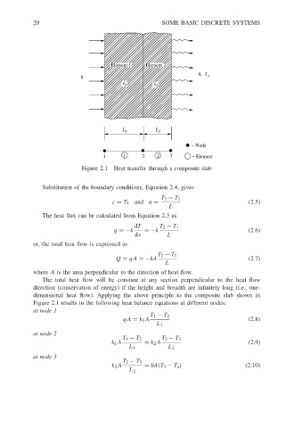
Figure 2.1 Heat transfer through a composite slab
Substitution of the boundary conditions, Equation 2.4, gives
T 2 − T 1
c = T 1 and a = (2.5)
L
The heat flux can be calculated from Equation 2.3 as
dT T 2 − T 1
q =−k =−k (2.6)
dx L
or, the total heat flow is expressed as
T 2 − T 1
Q = qA =−kA (2.7)
L
where A is the area perpendicular to the direction of heat flow.
The total heat flow will be constant at any section perpendicular to the heat flow
direction (conservation of energy) if the height and breadth are infinitely long (i.e., one-
dimensional heat flow). Applying the above principle to the composite slab shown in
Figure 2.1 results in the following heat balance equations at different nodes:
at node 1
T 1 − T 2
qA = k 1 A (2.8)
L 1
at node 2
T 1 − T 2 T 2 − T 3
k 1 A = k 2 A (2.9)
L 1 L 2
at node 3
T 2 − T 3
k 2 A = hA(T 3 − T a ) (2.10)
L 2