Page 44 - Fundamentals of The Finite Element Method for Heat and Fluid Flow
P. 44

SOME BASIC DISCRETE SYSTEMS
                        36
                                                                       T a = 25 °C
                                       2mm                       6cm
                                                                                2
                                                                       h = 100 W/m K
                                                                       k = 200 W/mK
                                                8mm 8mm 8mm
                                                                8mm
                                                          100 °C
                                                  Figure 2.16 A heat sink


                                                                                              2
                        (c) overall heat transfer coefficient U = 600 W/m 2 ◦ C (d) heat exchanger area A = 4m (e)
                                                      ◦
                        cold fluid entry temperature T ci = 20 C (f) hot fluid entry temperature T hi = 80 C. Set up
                                                                                         ◦
                        the stiffness matrix and hence solve for the outlet temperature and the effectiveness of the
                        heat exchanger by using 1 element, 2 elements and 4 elements for the heat exchanger. Also
                        determine the minimum number of elements required for converged solution.

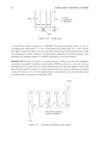
                        Exercise 2.5.13 Figure 2.17 shows an arrangement for cooling of an electronic equipment
                        consisting of a number of printed circuit boards (PCBs) enclosed in a box. Air is forced
                        through the box by a fan. Select a typical element and write down the stiffness matrix and
                        show that this method can take care of non-uniform flow (by using the methodology similar
                        to that in Exercise 2.5.9, the non-uniform flow in each channel can be determined) and
                        non-uniform heat generation in individual PCB.


                                                                             Air out


                                                        PCB with heat-generating
                                                        electronic components


                                        Air in
                                         Figure 2.17 Assembly of printed circuit boards
   39   40   41   42   43   44   45   46   47   48   49