
Page 173 - Fundamentals of Water Treatment Unit Processes : Physical, Chemical, and Biological
P. 173
128 Fundamentals of Water Treatment Unit Processes: Physical, Chemical, and Biological
6.3 Plain Sedimentation—Iso-Percent Removals for
Q(tube) Discrete Particle Suspension
Q(tube) Given=Required
For a discrete particle suspension, explain how the
iso-concentration lines are determined. Extend this to
a depth versus time plot that shows iso-concentration
lines.
6.4 Total Removal of Particles for Hypothetical Basin
Given
Referring to Figure 6.11, consider the particles shown at
the entrance to basin as representative of the suspension.
Required
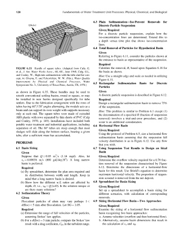
FIGURE 6.35 Bundle of square tubes. (Adapted from Culp, G. Calculate the removal, R, based upon Equation 6.18 for
et al., J. Am. Water Works Assoc., 60, 681, June 1968; Culp, G.L. the basin as shown.
and Conley, W., High-rate sedimentation with the tube clarifier con-
Hint: Use a straight-edge and scale as needed in utilizing
cept, in: Gloyna, E. and Eckenfelder, W. W. (Eds.), Water Quality
Figure 6.11.
Improvement by Physical and Chemical Processes, Water
6.5 Rectangular Sedimentation Basin for Discrete
Symposium No. 3., University of Texas Press, Austin, TX, 1970.)
Particles
as shown in Figure 6.35. These bundles may be used to Given
retrofit conventional settling basins, round or square, or may A discrete particle suspension is described in Figure 6.12.
be installed in new basins designed specifically for tube Required
settlers. Due to the fabrication arrangement with the rows of Design a rectangular sedimentation basin to remove 75%
tubes having 608=1208 angles alternating, the module acts as a of the suspension.
beam and can support its own weight with supports necessary
Hint: This problem is similar to Problem 6.1 except (1)
only at each end. The square tubes were made of extruded
the determination of a specified R (fraction of suspension
ABS plastic with rows separated by thin sheets of PVC (Culp
removed) involves a trial-and-error procedure, and (2)
and Conley, 1970, p. 149). Installations have included both scour is an additional consideration.
potable water treatment and industrial applications, including 6.6 Horizontal Flow Basin
separation of oil. The 608 tubes are steep enough that most
Given=Required
sludges will slide along the bottom surface, bearing a given
Using the protocol of Problem 6.5, size a horizontal flow
tube, after a sufficient mass has accumulated.
sedimentation basin assuming that the suspension fall
velocity distribution is as in Figure 6.12. Use any flow
PROBLEMS
that you wish.
6.1 Basin Sizing 6.7 Using Suspension Test Results to Design an Ideal
Given Basin
3
Suppose that Q ¼ 0.05 m =s (1.14 mgd). Also, let Given=Required
2
v o ¼ 0.00038 m=s (800 gal=day=ft ). A long narrow Determine the overflow velocity required for a 0.70 frac-
basin is preferred. tion removal of the suspension characterized by Figure
Required 6.12. Determine the dimensions of a horizontal-flow
(a) By spreadsheet, determine the plan area required and basin for this result. Use Shield’s equation to determine
its distribution between width and length. Keep in maximum horizontal velocity. The proportion of suspen-
mind that a long narrow basin is desired. sion scoured is removed from the net deposit.
(b) Show how the different w=L ratios are affected by 6.8 Spreadsheet for Basin Sizing
depth, D, i.e., v H ¼ Q=(wD). Is the solution unique or Given=Required
are there many solutions? Set up a spreadsheet to accomplish a basin sizing for
6.2 Sedimentation Theory different scenarios, with calculation of corresponding
Given removals.
Flocculent particles of alum may vary perhaps 1 < 6.9 Sizing Horizontal Flow Basin—Two Approaches
d(floc) < 5 mm after flocculation. Let SG ¼ 1.05. Given=Required
Required Examine the sizing of a horizontal flow sedimentation
(a) Determine the range of fall velocities of the particles, basin recognizing two basic approaches:
assuming Stokes’ law applies. a. Assume velocities (overflow and then horizontal flow).
(b) For a d(floc) ¼ 5 mm particle, compare the Stokes’ law b. Alternatively, assume basin dimensions that result in
result with a drag coefficient, C D , in the turbulent range. the calculation of v o and v H .