
Page 168 - Fundamentals of Water Treatment Unit Processes : Physical, Chemical, and Biological
P. 168
Sedimentation 123
Shear force Shear force
mgcosθ (c) mgcosθ
θ
(a) (b) mg
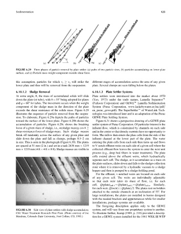
FIGURE 6.29 Three phases of particle removal by plate settler: (a) paths of two particle sizes, (b) particles accumulating on lower plate
surface, and (c) Particle mass weight component exceeds shear force.
this assumption, particles for which v s v o will strike the different stages of accumulation across the area of any given
lower plate and thus will be removed from the suspension. plate. Several clumps are seen falling below the plates.
6.10.1.2 Sludge Removal 6.10.1.3 Plate Settler Systems
At some angle, u, the mass of accumulated solids will slide Plate settlers were introduced into the market about 1970
down the plate (or tube), with u ¼ 558 being adopted for plates (Yao, 1973) under the trade names, Lamella Separatore
and q ¼ 608 for tubes. The movement occurs when the weight (Parkson Corporation) and GEWEe Lamella Sedimentation
component of the sludge mass in the direction of the plate System (Purac Corporation, www.lackebywater.se=inc=pdf=
exceeds the shear resistance of the solids mass. Figure 6.29 en_purac_gewe.pdf). The SuperSettlere of WaterLink Tech-
illustrates the sequence of particle removal from the suspen- nologies was introduced later and is an adaptation of the Purac
sion. To elaborate, Figure 6.29a depicts the paths of particles GEWE Plate Settling System.
toward the surface of the lower plate. Figure 6.29b shows the Figure 6.31 shows a perspective drawing of a GEWE plate
accumulation of particles. Figure 6.29c shows the breaking settler system of Purac Corporation. Of particular interest is the
influent flow, which is constrained by channels on each side
loose of a given mass of sludge, i.e., m(sludge mass)g cos u
shear-resistance-force-of-sludge-mass. Such sludge masses and in the center so that density currents have no opportunity to
break off randomly across the surface of any given plate and form. The inflow then enters the plate cells from the side of the
slide down the plate and fall as clumps, perhaps 0.5–2cm influent channel at the lower part of the plate. The water
in size. This is seen in the photograph (Figure 6.30). The plates entering the plate cells from each side then turns up and flows
are spaced at 51 mm (2 in.) and set in a tank 2438 mm 1219 to V-notch effluent weirs on each side of a given cell where the
mm 1219 mm (4 ft 4ft 8 ft). Sludge masses are visible in collected effluent flow leaves the system to enter the next unit
process (e.g., deep bed filters in water treatment). The plate
cells extend above the effluent weirs, which hydraulically
separate each cell. The sludge, as it accumulates as a mass on
the plate surfaces, slides down and falls to the sludge-collection
zone where it is removed by a hydraulic vacuum to a sludge
hopper and then is pumped to a sludge-holding pond.
For the effluent, v-notched weirs are located on each side
of any given cell. The weirs are individually adjustable
so that each weir takes its share of flow, i.e. for each
cell, Q(plate) cell 1 ¼ Q(plate) cell 2 ¼ Q(plate) cell n . Similarly,
for each weir, Q(weir) ¼ Q(plate)=2. The plates rest on holders
attached to the outside channels at an inclination of 558. For
large installations, the plates are installed in basins designed
with the needed brackets and appurtenances while for smaller
installations, package systems are available.
The foregoing description applies only to the GEWE
FIGURE 6.30 Side view of plate settlers with sludge accumulation; system, and will vary from one proprietary system to another.
CSU Water Treatment Research Pilot Plant. (Photo courtesy of Joe To illustrate further, Kamp (1989, p. 210) provided a descrip-
Mendoza, Colorado State University, Fort Collins, CO, 1995.) tion for a GEWE system installed for the 1981 WRK III WTP