
Page 167 - Fundamentals of Water Treatment Unit Processes : Physical, Chemical, and Biological
P. 167
122 Fundamentals of Water Treatment Unit Processes: Physical, Chemical, and Biological
6.9.3 SUMMARY NOTES FOR PRACTICAL DESIGN
BOX 6.4 ON PLATE SETTLERS
Camp (1946, 1953) departed from the conventional wisdom
Two of the Swedish companies that market plate settlers
in a number of areas. His ideas are worth summarizing: first,
are Purac and Parkson. Originally there was one com-
because they reinforce basic concepts of basin design and,
pany, Axel Johnson, which was family owned. In the
second, because of his credibility regarding settling theory
1950s, however, Purac was formed by some of the family
and practice. Camp advocated long narrow basins to reduce
members and the two companies each have established
the effects of hydraulic factors. For final settling, Camp
identities in the same field of business and both produce
suggested shallower basins. In deep tanks, he noted, the
plate settlers. At the same time, Waterlink Technologies
activated sludge plunges along the bottom of the basin and
was a part of Nordic Water Products AB, formerly an
then upturns at the end (see also Kawamura (1996) and Esler
Axel Johnson company (Waterlink Technologies, 1997),
(1998)). With a shallow rectangular basin, integrated with the
which produced a plate-settler system similar to the Purac
activated sludge reactor, the flow is distributed better initially
system after the Purac patent expired. According to the
and the suspension passes through the settling phases, i.e.,
Waterlink annual report (from a January 10, 2008 google
Type II, then Type III further, and finally Type IV at the
search on plate settlers), Waterlink was formed in
bottom. Concerning effluent launders, Camp (1953) sug-
December 1995 as a holding company to consolidate
gested placing them concurrent with flow and across (forming
various individual companies to form a comprehensive
a grid) and into the basin in order to draw the flow from the
company that could offer a complete array of services,
clarified zone and away from the sludge upturn-back roll.
including a ‘‘design-build’’ service. According to the
Finally, Camp suggested withdrawing the sludge at the
report, they acquired Purac in 1998. Their annual report
effluent end.
listed a number of companies that comprised the overall
company, perhaps on the same order of size as U.S.
Filter, Infilco-Dregemont, Vivendi, and others.
6.10 PLATE SETTLERS AND TUBE SETTLERS
Inclined plate and tube settlers have evolved over the years.
where
The concept started with Hazen in 1904 as horizontal ‘‘tray
~ v s is the fall velocity of any particle (m=s)
settlers’’ and then was advanced further by Camp (1946,
~ v P is the advection velocity of water flow between plates of
1953) and implemented in Sweden in the 1950s (Fischer-
settler (m=s)
ström, 1955). Sludge removal was the problem, however,
~ v R is the vector sum of fall velocity of particle and advec-
since the plates were horizontal. The answer was found by
tion velocity of water (m=s)
tilting the plates so that, after some amount of accumulation of
mass, the solids would slide from the surface by gravity. Tube
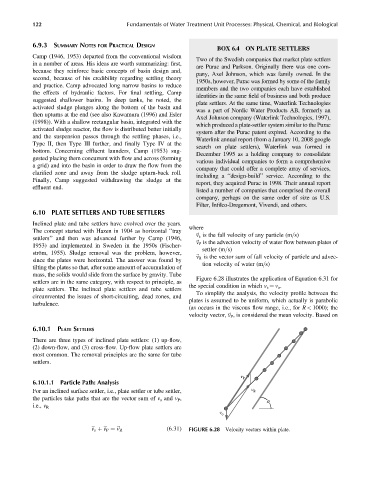
Figure 6.28 illustrates the application of Equation 6.31 for
settlers are in the same category, with respect to principle, as
the special condition in which v s ¼ v o .
plate settlers. The inclined plate settlers and tube settlers
To simplify the analysis, the velocity profile between the
circumvented the issues of short-circuiting, dead zones, and
plates is assumed to be uniform, which actually is parabolic
turbulence.
(as occurs in the viscous flow range, i.e., for R < 1000); the
velocity vector,~ v P , is considered the mean velocity. Based on
6.10.1 PLATE SETTLERS
There are three types of inclined plate settlers: (1) up-flow,
(2) down-flow, and (3) cross-flow. Up-flow plate settlers are
most common. The removal principles are the same for tube
settlers.
v P
6.10.1.1 Particle Path: Analysis
For an inclined surface settler, i.e., plate settler or tube settler, v R
the particles take paths that are the vector sum of v s and v P ,
θ
i.e., v R
v o
~ v s þ~ v P ¼~ v R (6:31) FIGURE 6.28 Velocity vectors within plate.