
Page 164 - Fundamentals of Water Treatment Unit Processes : Physical, Chemical, and Biological
P. 164
Sedimentation 119
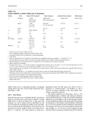
TABLE 6.10
Design Guidelines or Basins Settling Type II Suspensions
Criteria Units Primary WW Treatment a Water Treatment Up-Flow Water Treatment Solids Contact
3
m =min=m 2 <0.028 b 0.0006–0.0017 c 0.0009–0.0013 c 0.0014–0.0021 c
v o
0.005–0.028 d,a 0.022–0.026 alum floc g
0.012–0.046 e,f
gpm=ft 2 <0.69 b 0.015–0.04 0.5–0.75 c 0.8–1.2 c
0.14–0.69 d,a 0.53–0.65 alum floc g
0.31–1.12 e,f
gpm=ft 2 0.34–1.0 c 0.5–0.75 c 0.8–1.2 c
m=min Shield’s equation 0.9 h NA
v H
ft=min <2 i 3
u h 1–4 j 1.5–3 c 1–3 c 1–2 c
1–2 i
k
L=w ¼ 20 >1=5 NA
3
Weir loading m =min=m 0.10–0.25 l 0.18 c 0.12 c 0.12–0.25 c
m
0.87–0.25
gpm=ft 2.11–6.34 l <15 c 10 c 10–20 c
6.94–20.1 m
n
Depth (D) m 1–5 ; >2.1 o 3–5 c 3–5 c
n
ft 3–15 ; >7 o 10–16 c 10–16 c
7–12 i
a
Primary settlers are sized on overflow rate alone.
b
Does not distinguish between rectangular and circular (WPCF, 1985).
c
Kawamura and Lang (1986) for chemical floc in water treatment plants.
d
Camp (1953).
e 2 2
Chemical sedimentation 0.31–1.12 gpm=ft for iron and polymer coagulated primary sewage, generally v o ¼ 0.69 gpm=ft , T ¼ 2h.
f
The upper limit rate to lime floc which is used most often tertiary treatment; lime floc settles 1–4 times greater than alum flocs.
g 3 2 2
Surface loading rates 0.52–0.63 m =min=m (0.53–0.65 gpm=ft ) were recommended (for an alum floc suspension).
h
Shield’s equation is recommended.
i
European practice uses v H < 0.61 m=min (2 ft=min) for rectangular basins, with D=L 1=10 to 1=30, with w ¼ 6.1–9.1 m (20–30 ft) and depths 1.5–3.0 m
(5–10 ft). In lieu of specifying v H , American practice uses depths 2.1–3.7 m (7–12 ft) with u ¼ 1–2h.
j
Value dependent on flow and suspension to be settled; data from primary clarifiers at Denver showed marked reduction in suspended solids removal at
higher overflow velocities.
k
Camp (1953) suggests that L=w ¼ 20, such that inlet and outlet zones are about 10% of tank length with settling zone about 90%.
l
Weir loading rates for primary settling tanks in wastewater treatment; circular tanks fall in this range for flows (WPCF, 1985). According to some authorities,
weir loading is not as important as weir placement and tank design.
m
Weir rates 7.64–20.1 gpm=ft depending on nature of chemical solids.
n
Deeper clarifiers are recommended but the question of depth is debated.
o
Burns and Roe (1971).
further, Figure 6.24 is a photograph showing a rectangular spreadsheet model, the flow across any orifice (or slot) is
0.5
settling basin at the City of Fort Collins Wastewater Treat- Q(orifice) ¼ C A(orifice)(2gDh) . The headloss, i.e., Dh,is
ment Plant, c. 1996. equal for all orifices regardless of the orifice depth. Also,
v(orifice) ¼ Q(orifice)=A(orifice).
Inlet diffuser guidelines are (Kawamura, 1996, p. 132)
6.9.1 INLET DESIGN
(1) a distribution plate, or diffuser wall, with ports should be
The goal of the inlet zone is to distribute the flow such that the used to distribute the flow; (2) the ports should be distributed
entire cross-sectional area of the basin is utilized. A slotted uniformly across the diffuser wall; (3) the maximum number
baffle device, as shown in Figure 6.25, is often used. The of ports should be provided so that dead zones between ports
openings, e.g., slots or orifices, must be distributed over the are minimized; (4) the headloss across the diffuser wall should
cross-sectional area; the higher the headloss across the baffle, be 0.3–0.9 mm to equalize the flow distribution with minimal
the more uniform the flow distribution. At the same time, the floc breakage; (5) the size of the ports should be uniform and
associated jet velocity is higher, which is not desired, and so large enough, i.e., 75–150 mm, to avoid clogging by algae
there is a ‘‘trade-off.’’ For ready reference in setting up a and other matter; (6) the ports should be spaced 250–400 mm