
Page 159 - Fundamentals of Water Treatment Unit Processes : Physical, Chemical, and Biological
P. 159
114 Fundamentals of Water Treatment Unit Processes: Physical, Chemical, and Biological
6 given basin and to predict the dispersion curve (see also Box
F
6.1). The use of such software requires knowledge of
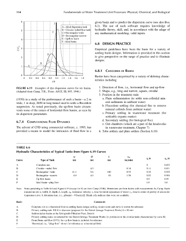
A—Ideal dispersion tank
5 B—Circular radial flow tank hydraulic theory, skill, and, in accordance with the adage of
E C—Rectangular-wide any mathematical modeling, valid inputs.
D—Rectangular-narrow
4 E—Upflow basin
F—Ideal basin
6.8 DESIGN PRACTICE
C/C o 3 Empirical guidelines have been the basis for a variety of
settling basin designs. Information is provided in this section
D
to give perspective on the range of practice and to illustrate
2
C designs.
B
1 A
6.8.1 CATEGORIES OF BASINS
0 Basins have been categorized by a variety of defining charac-
0 0.2 0.4 0.6 0.8 1.0 1.2 1.4 1.6 1.8
teristics including
t/θ
FIGURE 6.19 Examples of dye dispersion curves for six basins. 1. Direction of flow, i.e., horizontal flow and up-flow
(Adapted from Camp, T.R., Trans. ASCE, III, 895, 1946.) 2. Shape, e.g., long and narrow, square, circular
3. Position in the treatment train
(1930) in a study of the performance of such a basin—a2 m a. Plain sedimentation (to settle non-colloidal min-
wide, 1 m deep, 2650 m long tunnel used to settle a flocculent eral sediments in ambient water)
suspension. As noted previously, the up-flow basin circum- b. Flocculent settling (for chemical floc to remove
vents some of the issues of horizontal-flow basins, as seen by mineral colloids from ambient water)
its dispersion parameters. c. Primary settling in wastewater treatment (for
settleable organic matter)
d. Secondary settling (for biological floc)
6.7.4 COMPUTATIONAL FLUID DYNAMICS
e. Grit chambers (which are a part of the headworks
The advent of CFD using commercial software, c. 1995, has in wastewater treatment, Chapter 7)
provided a means to model the intricacies of fluid flow in a 4. Tube settlers and plate settlers (Section 6.10)
TABLE 6.6
Hydraulic Characteristics of Typical Tanks from Figure 6.19 Curves
w D L v H
Curve Type of Tank (m) (m) (m) (m=min) t i =u t A =u
A Complete mix 0 0.693
B Circular—radial flow 4.3 0.34 0.14 0.831
C Rectangular—wide 41.1 5.6 100 0.95 0.30 0.925
D Rectangular—narrow 4.9 4.3 83 1.58 0.52 0.903
E Up-flow basin 0.5 0.95
F Ideal basin—plug flow 1.0 1.0
Note: Notes pertaining to Table 6.6 and Figure 6.19 (except for E) are from Camp (1946), Dimensions are from basins with measurements by Camp. Basin
dimensions are w, width; D, depth; L, length, v H , horizontal velocity; t i , time for initial appearance of tracer; t A , time to center of gravity of area under
dispersion curve; u, detention time, i.e., q(basin) ¼ V(basin)=Q. Blank cells indicate data were not available.
Basin Comments
A Complete mix is a theoretical limit in settling basin design; settling cannot occur and curve is shown for reference
B Primary settling tank 200 ft in diameter (proposed for the Detroit Sewage Treatment Works) u ¼ 90 min
C Sedimentation basins at the Springwells Filtration Plant, Detroit
D Primary settling tanks constructed for the Detroit Sewage Treatment Works (in preference to the circular tanks characterized by curve B)
E From Burns and Roe (1971); the up-flow basin is included for reference
F Theoretical, i.e., ‘‘plug-flow’’ shown for reference as a theoretical limit