
Page 154 - Fundamentals of Water Treatment Unit Processes : Physical, Chemical, and Biological
P. 154
Sedimentation 109
6.6.2.1 Activated Sludge R is the return flow of water back to the reactor with solids
3
A ‘‘conventional’’ activated sludge system consists of a suspension (m =s)
reactor and a final settling basin, which are illustrated sche- X is the concentration of solids in the reactor and those
3
matically in Figure 6.16. The flows of various water suspen- entering the final settling basin (kg solids=m )
sions are shown by arrows; terms are defined in the drawing.
The recycle of a thickened sludge, i.e., bacterial cells, back to The solids flux leaving the basin in the underflow is
the reactor, serves as a part of the reaction between the cells at
J(solids) out ¼ (R þ W) X r (6:22)
concentration, X, in the reactor and biodegradable wastes at
concentration, S. The product of the rate of recycle flow, R,
where
and the cell concentration, X r , in the thickened underflow
J(solids) out is the mass flux of solids into the final settling
determines, in part, the concentration, X, in the reactor (see
basin in underflow (kg solids=s)
Section 23.2.2 and Equation 23.14). In principle, the higher
W is the waste flow of water-solids suspension leaving the
the value of X, the faster the reaction rate; a usual achievable 3
system (m =s)
target is X 2000–2500 mg=L. As seen in Figure 6.16, final
X r is the concentration of solids in the underflow leaving
settling is an integral part of an activated sludge system. 3
the final settling basin (kg solids=m )
6.6.2.2 Final Settling Basin Processes Equating (6.21) and (6.22) is a mass balance on the final
As depicted in Figure 6.16 the final settling basin has two zones: settling basin, as seen in (23.14). The mass balance shows the
(1) settling and (2) thickening. First, the incoming cells from the relationship between the variables, illustrating the importance
reactor, comprising a Type III suspension, must be separated of final settling to achieve a high X t and thus a higher X in
from the water to produce a clarified effluent that meets regu- the reactor.
latory requirements, e.g., X e 30 mg=L. Second, the cells that Actually, J(solids) inflow ¼ J(solids) underflow þ (Q W)X e ,
have settled, comprising a Type IV suspension, must be ‘‘thick- but since X e 30 mg=L by regulation, the product (Q W)
ened’’ (Dick and Ewing, 1967). The thickened solid leaving the X e is considered negligible; therefore, we let J(solids) inflow
basin at concentration, X r , is often called the ‘‘underflow,’’ i.e., J(solids) underflow , so the two may be used interchangeably,
(R þ W ). The value of X r affects R, X, and W. As a rule, depending on the purpose of a relation.
6,000 < X r < 10,000 mg=L; X r ! 10,000 mg=L is a goal. An initial plan area for a basin, A(plan), is calculated from
the expression for overflow velocity, i.e., Equation 6.11:
6.6.2.3 Mass Balance Relations
(Q W) ¼ SOR A(plan) (6:23)
Referring to Figure 6.16, several mass balance relations for the SOR
final settling basin can be derived, which are useful for later
This value for A(plan) is used as a first trial for the calculation
reference. First, the mass flux of solids, J(solids), into the basin is
of the ‘‘bulk’’ velocity of water, u, as it falls in the basin, i.e.,
J(solids) ¼ (Q þ R) X (6:21) (R þ W) ¼ u A(plan) underflow (6:24)
in
where where
J(solids) in is the mass flux of solids into the final settling u is the bulk velocity of water falling vertically through the
basin (kg solids=s) basin (m=s)
3
2
Q is the flow of water to the system (m =s) A(plan) is the plan area of the basin (m )
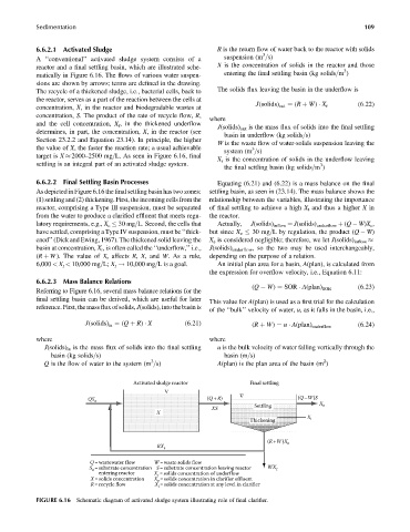
Activated sludge reactor Final settling
QS o (Q +R) (Q –W)S
Settling X e
XS
X
X
Thickening i
(R+W)X r
RX r
Q=wastewater flow W=waste solids flow
=substrate concentration S=substrate concentration leaving reactor WX
S o r
entering reactor X = solids concentration of underflow
r
X= solids concentration X e = solids concentration in clarifier effluent
R= recycle flow X i = solids concentration at any level in clarifier
FIGURE 6.16 Schematic diagram of activated sludge system illustrating role of final clarifier.