
Page 160 - Fundamentals of Water Treatment Unit Processes : Physical, Chemical, and Biological
P. 160
Sedimentation 115
5. Solids contact basins in which the coagulated water Launder Effluent
passes through a blanket of solids, i.e., a chemical Inlet
floc
6. Flotation basins (Chapter 8)
7. Innovative technologies
a. Actiflowt process is an example in which sand is
attached by polymers to the flocculent material.
The higher specific gravity material incorporated
into the floc results in a markedly higher gravity Solids removal equipment
force and thus higher fall velocity.
8. Suspension category:
a. Discrete particle Solids removal
b. Flocculent particle
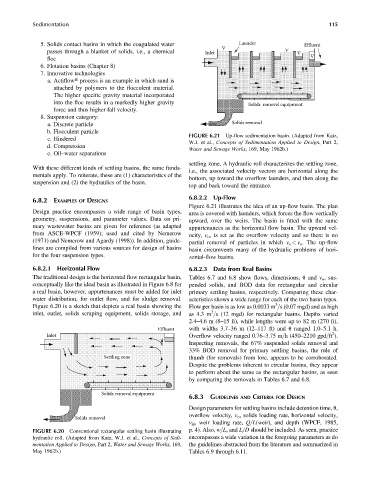
FIGURE 6.21 Up-flow sedimentation basin. (Adapted from Katz,
c. Hindered
W.J. et al., Concepts of Sedimentation Applied to Design, Part 2,
d. Compression
Water and Sewage Works, 169, May 1962b.)
e. Oil–water separations
settling zone. A hydraulic roll characterizes the settling zone,
With these different kinds of settling basins, the same funda-
i.e., the associated velocity vectors are horizontal along the
mentals apply. To reiterate, these are (1) characteristics of the
bottom, up toward the overflow launders, and then along the
suspension and (2) the hydraulics of the basin.
top and back toward the entrance.
6.8.2.2 Up-Flow
6.8.2 EXAMPLES OF DESIGNS
Figure 6.21 illustrates the idea of an up-flow basin. The plan
Design practice encompasses a wide range of basin types, area is covered with launders, which forces the flow vertically
geometry, suspensions, and parameter values. Data on pri- upward, over the weirs. The basin is fitted with the same
mary wastewater basins are given for reference (as adapted appurtenances as the horizontal flow basin. The upward vel-
from ASCE-WPCF (1959); used and cited by Nemerow ocity, v o , is set as the overflow velocity and so there is no
(1971) and Nemerow and Agardy (1998)). In addition, guide- partial removal of particles in which v s < v o . The up-flow
lines are compiled from various sources for design of basins basin circumvents many of the hydraulic problems of hori-
for the four suspension types. zontal-flow basins.
6.8.2.1 Horizontal Flow 6.8.2.3 Data from Real Basins
The traditional design is the horizontal flow rectangular basin, Tables 6.7 and 6.8 show flows, dimensions, u and v o , sus-
conceptually like the ideal basin as illustrated in Figure 6.8 for pended solids, and BOD data for rectangular and circular
a real basin, however, appurtenances must be added for inlet primary settling basins, respectively. Comparing these char-
water distribution, for outlet flow, and for sludge removal. acteristics shows a wide range for each of the two basin types.
3
Figure 6.20 is a sketch that depicts a real basin showing the Flow per basin is as low as 0.0033 m =s (0.07 mgd) and as high
3
inlet, outlet, solids scraping equipment, solids storage, and as 4.3 m =s (12 mgd) for rectangular basins. Depths varied
2.4–4.6 m (8–15 ft), while lengths were up to 82 m (270 ft),
Effluent with widths 3.7–36 m (12–117 ft) and u ranged 1.0–5.1 h.
2
Inlet Overflow velocity ranged 0.76–3.75 m=h(450–2210 gpd=ft ).
Inspecting removals, the 67% suspended solids removal and
33% BOD removal for primary settling basins, the rule of
Settling zone thumb (for removals) from lore, appears to be corroborated.
Despite the problems inherent to circular basins, they appear
to perform about the same as the rectangular basins, as seen
by comparing the removals in Tables 6.7 and 6.8.
Solids removal equipment
6.8.3 GUIDELINES AND CRITERIA FOR DESIGN
Design parameters for settling basins include detention time, u,
overflow velocity, v o , solids loading rate, horizontal velocity,
Solids removal
v H , weir loading rate, Q=L(weir), and depth (WPCF, 1985,
FIGURE 6.20 Conventional rectangular settling basin illustrating p. 4). Also, w=L,and L=D should be included. As seen, practice
hydraulic roll. (Adapted from Katz, W.J. et al., Concepts of Sedi- encompasses a wide variation in the foregoing parameters as do
mentation Applied to Design, Part 2, Water and Sewage Works, 169, the guidelines abstracted from the literature and summarized in
May 1962b.) Tables 6.9 through 6.11.