
Page 163 - Fundamentals of Water Treatment Unit Processes : Physical, Chemical, and Biological
P. 163
118 Fundamentals of Water Treatment Unit Processes: Physical, Chemical, and Biological
parameter criteria for basins settling Type II suspensions, with
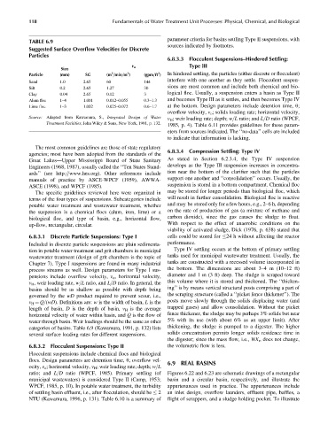
TABLE 6.9
sources indicated by footnotes.
Suggested Surface Overflow Velocities for Discrete
Particles
6.8.3.3 Flocculent Suspensions–Hindered Settling:
v o Type III
Size
2
3
2
Particle (mm) SG (m =min=m ) (gpm=ft ) In hindered settling, the particles (either discrete or flocculent)
interfere with one another as they settle. Flocculent suspen-
Sand 1.0 2.65 60 144
Silt 0.2 2.65 1.27 30 sions are most common and include both chemical and bio-
Clay 0.04 2.65 0.12 3 logical floc. Usually, a suspension enters a basin as Type II
Alum floc 1–4 1.001 0.012–0.055 0.3–1.3 and becomes Type III as it settles, and then becomes Type IV
Lime floc 1–3 1.002 0.025–0.072 0.6–1.7 at the bottom. Design parameters include detention time, u;
overflow velocity, v o ; solids loading rate; horizontal velocity,
Source: Adapted from Kawamura, S., Integrated Design of Water v H ; weir loading rate; depth; w=L ratio; and L=D ratio (WPCF,
Treatment Facilities, John Wiley & Sons, New York, 1991, p. 132.
1985, p. 4). Table 6.11 provides guidelines for these param-
eters from sources indicated. The ‘‘no-data’’ cells are included
to indicate that information is lacking.
The most common guidelines are those of state regulatory
agencies; most have been adopted from the standards of the 6.8.3.4 Compression Settling: Type IV
Great Lakes—Upper Mississippi Board of State Sanitary As stated in Section 6.2.3.4, the Type IV suspension
Engineers (1968, 1987), usually called the ‘‘Ten States Stand- develops as the Type III suspension increases in concentra-
ards’’ (see http:==www.hes.org). Other references include tion near the bottom of the clarifier such that the particles
manuals of practice by ASCE-WPCF (1959), AWWA- support one another and ‘‘consolidation’’ occurs. Usually, the
ASCE (1998), and WPCF (1985). suspension is stored in a bottom compartment. Chemical floc
The specific guidelines reviewed here were organized in may be stored for longer periods than biological floc, which
terms of the four types of suspensions. Subcategories include will result in further consolidation. Biological floc is reactive
potable water treatment and wastewater treatment, whether and may be stored only for a few hours, e.g., 2–6 h, depending
the suspension is a chemical flocs (alum, iron, lime) or a on the rate of production of gas (a mixture of methane and
biological floc, and type of basin, e.g., horizontal flow, carbon dioxide), since the gas causes the sludge to float.
up-flow, rectangular, circular. With respect to the effect of anaerobic conditions on the
viability of activated sludge, Dick (1976, p. 638) stated that
6.8.3.1 Discrete Particle Suspensions: Type I cells could be stored for 24 h without affecting the reactor
Included in discrete particle suspensions are plain sedimenta- performance.
tion in potable water treatment and grit chambers in municipal Type IV settling occurs at the bottom of primary settling
wastewater treatment (design of grit chambers is the topic of tanks used for municipal wastewater treatment. Usually, the
Chapter 7). Type I suspensions are found in many industrial tanks are constructed with a recessed volume incorporated in
process streams as well. Design parameters for Type I sus- the bottom. The dimensions are about 3–4 m (10–12 ft)
pensions include overflow velocity, v o , horizontal velocity, diameter and 1 m (3 ft) deep. The sludge is scraped toward
v H , weir loading rate, w=L ratio, and L=D ratio. In general, the this volume where it is stored and thickened. The ‘‘thicken-
basins should be as shallow as possible with depth being ing’’ is by means vertical structural posts comprising a part of
governed by the wD product required to prevent scour, i.e., the scraping structure (called a ‘‘picket fence thickener’’). The
v H ¼ Q=(wD). Definitions are: w is the width of basin, L is the posts move slowly through the solids displacing water (and
length of basin, D is the depth of basin, v H is the average trapped gases) and allow consolidation. Without the picket
horizontal velocity of water within basin, and Q is the flow of fence thickener, the sludge may be perhaps 3% solids but near
water through basin. Weir loadings should be the same as other 5% with its use (with about 6% as an upper limit). After
categories of basins. Table 6.9 (Kawamura, 1991, p. 132) lists thickening, the sludge is pumped to a digester. The higher
several surface loading rates for different suspensions. solids concentration permits longer solids residence time in
the digester; since the mass flow, i.e., WX r , does not change,
6.8.3.2 Flocculent Suspensions: Type II the volumetric flow is less.
Flocculent suspensions include chemical flocs and biological
flocs. Design parameters are detention time, u; overflow vel-
6.9 REAL BASINS
ocity, v o ; horizontal velocity, v H ; weir loading rate; depth; w=L
ratio; and L=D ratio (WPCF, 1985). Primary settling (of Figures 6.22 and 6.23 are schematic drawings of a rectangular
municipal wastewaters) is considered Type II (Camp, 1953; basin and a circular basin, respectively, and illustrate the
WPCF, 1985, p. 10). In potable water treatment, the turbidity appurtenances used in practice. The appurtenances include
of settling basin effluent, i.e., after flocculation, should be 2 an inlet design, overflow launders, effluent pipe, baffles, a
NTU (Kawamura, 1996, p. 131). Table 6.10 is a summary of flight of scrappers, and a sludge holding pocket. To illustrate