
Page 165 - Fundamentals of Water Treatment Unit Processes : Physical, Chemical, and Biological
P. 165
120 Fundamentals of Water Treatment Unit Processes: Physical, Chemical, and Biological
TABLE 6.11
Design Guidelines for Basins with Hindered Settling
Criteria Units Rectangular a Up-Flow Solids Contact Sludge Thickening
3
m =min=m 2 0.0028–0.034 b No data No data No data
v o
0.028–0.085 c
0.0226 d
gpm=ft 2 0.069–0.83 b No data No data No data
0.69–2.08 c
<0.55 d
v H m=min No data NA NA NA
ft=min
u h 2–3 e No data No data No data
L=w No data NA No data No data
3
Weir loading m =min=m 0.086–0.258 f No data No data No data
g
0.283–0.424
gpm=ft 6.94–20.8 f x x x
g
6.94–10.4
D m 2.4–4.6 h No data No data No data
ft 8–15 h,d
Solids loading kg=day=m 2 245 i No data No data No data
lb=day=ft 2 50
a 2 2
Secondary settler design based on overflow rate and solids loading, i.e., kg dry solids=day=m (lb dry solids=day=ft ), see Dick (1970). Solids loading can be
obtained from lab settling tests. Areas based on settling and solids loading are compared and the larger is used.
b 3 2 2
Recommended v o 0.023 m =min=m (0.55 gpm=ft ); temperatures of 08C decreases v s by a factor of about 1.75 compared with 208C (WPCF, 1985).
c
Final settling should be designed on the basis of overflow velocity rather than detention time, with allowances for the depth of sludge blanket for activated
sludge final settling (Camp 1953).
d 2
Secondary settlers are quite different than primary settlers due to the amount and nature of the solids. Ten States Standards v o ¼ 0.55 gpm=ft and D > 8 ft.
e
Burns and Roe (1971).
f
Most sources indicate that weir placement is more important than weir loading; for center feed tanks, optimum weir location is about 0.67–0.75 of the radial
distance from the center (WPCF, 1985).
g 3 3 3
Weir loading (p. 7–8) is given as 0.28 m =min=m for <0.044 m =s(<6.94 gpm=ft for <1 mgd) and 0.42 m =min=m(<10.4 gpm=ft) for larger plants for
secondary settling.
h
Deeper basins are recommended for final settling of activated sludge; for large final clarifiers, the average depth was 4.6 m (15 ft) with range 3.7–6.2 m
(12–20 ft); studies showed that effluent concentration was lower as depth increased; other factors being equal (WPCF, 1985).
i 2 2
Maximum allowed by Ten States Standards 1978 edition. Recommended: 49 kg=day=m at SVI ¼ 300–290 kg=day=m at SVI ¼ 100.
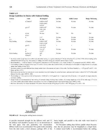
Influent Launders Effluent
Settling zone
Waste solids
FIGURE 6.22 Rectangular settling basin schematic.
to provide structural strength for the diffuser wall; and (7) basin length, and parallel to the side walls were found to
the diffuser wall should be located 1.8–2.1 m downstream of stabilize flow.
the inlet pipes. One and, preferably, two intermediate For flocculent settling that follows paddle wheel floccula-
diffuser walls were recommended. Two guide walls extending tion, the two processes may be integrated as a single basin.
from the inlet walls a short distance, perhaps 20% of the A slotted wood baffle is recommended before the settling,