
Page 166 - Fundamentals of Water Treatment Unit Processes : Physical, Chemical, and Biological
P. 166
Sedimentation 121
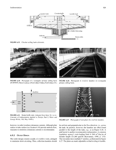
Launder/weir Circular baffle Launder/weir
Effluent
Solids thickening
Influent
Waste solids
FIGURE 6.23 Circular settling basin schematic.
FIGURE 6.24 Photograph of a rectangular primary settling basin FIGURE 6.26 Photograph of overflow launders for rectangular
(FCWWTP).PhotoCourtesy ofFortCollinsUtilities,FortCollins,CO.) primary settling basin.
Headloss
Inlet Settling zone
zone
Baffle
FIGURE 6.25 Slotted baffle inlet. (Adapted from Katz, W.J. et al.,
Concepts of Sedimentation Applied to Design, Part 2, Water and
Sewage Works, 169, May 1962b.) FIGURE 6.27 Photograph of weir plates for overflow launders.
however, in order to reduce extraneous currents. Although plate be uniform and perpendicular to the flow direction, i.e., across
settlers or tube settlers (see Section 6.10) provide uniform flow, the tank. In practice, however, the launders are often found
measures to minimize extraneous currents is recommended. parallel to the length of the tank, e.g., as in Figure 6.26. A
grid layout is another recommended configuration. A common
3
regulatory agency’s weir-loading limit is 264 m =day=mof
6.9.2 OUTLET DESIGN
launder length (21,260 gpd=ft) (Kawamura, 1996, p. 132).
The outlet design consists usually of overflow weirs, arranged The weir plates have multiple V-notches, as illustrated in Figure
to minimize short-circuiting. Thus, collection launders should 6.27. The plates are made adjustable so that leveling is feasible.