
Page 169 - Fundamentals of Water Treatment Unit Processes : Physical, Chemical, and Biological
P. 169
124 Fundamentals of Water Treatment Unit Processes: Physical, Chemical, and Biological
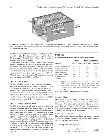
Effluent
Inlet flow
Inlet flow
Solids
FIGURE 6.31 Perspective of GEWE plate system. (Adapted from Hane-Weijman, H., Lamella separation—old technology in a modern
concept, Unpublished paper for short course Water Treatment Plant Design at Colorado State University, in June, 1991, Purac Engineering,
Inc., Wilmington, DE, 1991.)
3
at Enkhuizen, Holland with Q(max) ¼ 15,000 m =h or 4.17 TABLE 6.12
3
m =s (95 mgd). The dimensions were w(plate) ¼ 1.2 m
(3.9 ft), L(plate) ¼ 3 m (9.8 ft), u ¼ 558, d ¼ 80 mm (3.2 in.); Surface Overflow Rates—Plate Settler Installations
the plates were of stainless steel. Flow Surface Overflow Rate
Plate settlers have been used for a variety of municipal and 3 3 2 2
Location (m =s) (mgd) (m =m =day) (gpm=ft )
industrial installations. For Puract, as an example, some 400
installations were listed worldwide (Hane-Weijman, 1991) Andijk WRK III, Holland 4.16 95 38.7 0.66
that included municipal water treatment, municipal waste- Markis I, Yugoslavia 2.19 50 36.4 0.62
water treatment, and industrial wastewater treatment. The Ringssoverket, Sweden 1.18 27 24.1 0.41
3
listings included such diverse plants such as a 4.17 m =s Jezero, Yugoslavia 1.31 30 36.4 0.62
Fort Collins, Colorado 0.88 20 19.9 0.34
(95 mgd) waterworks at Enkhuizen, Holland, and at a cement Colorado Springs, 3.94 90 22.3 0.38
3
factory in Japan with 0.0020 m =s (32 gpm).
Colorado
6.10.1.4 Sizes of Units Source: Adapted from Hane-Weijman, H., Lamella separation—old
The sizes of plate systems depend upon the manufacturer, technology in a modern concept, Unpublished paper for short
course Water Treatment Plant Design at Colorado State
but typical dimensions are as follows: d ¼ 80 mm (3.2 in.),
University, in June, 1991, Purac Engineering, Inc., Wilmington,
L ¼ 3 m (9.8 ft), with w ¼ 1220 mm (4.0 ft), and u ¼ 558.
DE, 1991.
Plate spacing, d, depends upon the concentration of the suspen-
Note: SOR ¼ A(plan) ¼ Q(plate)=[L(plate) cos u w(plate)].
sion and varies from 51 to 102 mm (2–4 in.) (Hane-Weijman,
1991). For the Purac system, the effective plate length is about
2 m (6.6 ft) since the flow enters from the side about 1 m (3.2 ft) 6.10.1.6 Theory
from the bottom. In general, R < 100 for these systems.
Three types of plate settlers, as noted, are (1) up-flow,
(2) down-flow, and (3) cross-flow (Kamp, 1989; Hane-
6.10.1.5 Surface Overflow Rates Weijman, 1991) with particle trajectories illustrated by the
The SOR is the flow per unit area of plate as projected on vector diagrams of Figures 6.32, 6.33, and 6.34, respectively.
the horizontal plane and is an identity with v o , as seen in From these diagrams, the mathematical relationships between
Figure 6.28. The SOR is comparable to the same measure as v o and v P , and d and L can be determined.
used for horizontal flow basins. The calculation for a plate
6.10.1.6.1 Mathematics
settler is, v o ¼ SOR Q(plate)=[L(plate)cos q w(plate)], where
The mathematical relationships, based on similar triangles
Q(plate) ¼ Q(plate assembly)=[n(plates-in-assembly) 1].
between the velocity vectors (v o , v P ) and the plate geometry
For plate settlers, surface loading rates for several installa-
(d, L, u), are summarized below:
tions are given in Table 6.12. The SOR values are seen to vary
by a factor of nearly 2:1. For comparison, iron and alum floc
1. For up-flow, from Figure 6.32
at 108C settle at about 50 mm=min, i.e., 72 m=day (1.2
2
gal=min=ft ) (Yao, 1973, p. 624). For further reference, the
d= cos u
effluent turbidities from the plate settlers at Fort Collins are v o (6:32)
¼
0.1 NTU. v P L þ d=( cos u sin u)