
Page 201 - Fundamentals of Water Treatment Unit Processes : Physical, Chemical, and Biological
P. 201
156 Fundamentals of Water Treatment Unit Processes: Physical, Chemical, and Biological
Table CD7.14, Parts 1–3 provides a calculation algorithm Dp(pipe losses) is the pressure losses due to bends and
for Q(air) for different diffuser depths for each of the two appurtenances in pipeline (kPa)
diffuser types. k is the loss coefficient for appurtenance (a value of 0.1 is
common)
7.3.3.3 Pressure in Header Pipe Dp(valve) is the pressure loss across the air flow control
The absolute pressure in the header pipe is the sum of the valve (kPa)
2
atmospheric pressure plus the pressure at the depth of submer- Dp(valve) ¼ krv =2
gence of the diffuser plus the pressure loss across the diffuser, k is the coefficient that depends upon type of valve and
the latter being a function of Q a (diffuser). The pressure at outlet degree of closure and takes up the ‘‘slack’’ in Equation
of the blower equals the pressure in header pipe at the diffuser, 7.26
plus the pressure losses in the pipes and bends, plus the pres- Dp(water depth) is the pressure due to water depth, h (kPa),
sure loss across the airflow control valve. The relations are best which is calculated as the specific weight of water,
understood by sketching the ‘‘pneumatic’’ grade-line from the g(water), times the diffuser depth, h(diffuser)
ambient air pressure in the water above the tank to the ambient Dp(diffuser) is the pressure loss across diffuser (kPa)
air pressure at the blower intake. The mathematical relation is Dp(diffuser) ¼ Q(diffuser) ¼ CA(diffuser)[Dp(diffuser)] 0.5
C is the orifice coefficient (use 0.62 as a default value)
p(atmosphere) þ Dp(compressor) Dp(pipe friction)
The ‘‘pneumatic’’ grade-line is an extension of the
Dp(pipe losses) Dp(valve)
‘‘hydraulic’’ grade-line concept, which depicts water pressure
¼ p(atmosphere) þ Dp(water depth) þ Dp(diffuser)
in terms of ‘‘head’’ of water (meters or feet). The ‘‘pneumatic’’
(7:26) grade-line does the same thing but depicts absolute air pres-
sure (kPa or psi); alternatively, a manometer could be tapped
where into a pipe to measure the relative pressure of the gas as mm
p(atmosphere) is the barometric pressure or standard pres- of water.
sure at a given elevation (kPa)
Dp(compressor) is the pressure gain across the compressor 7.3.3.4 Blower Power
(kPa) The power required of a blower is given by the equation for an
Dp(pipe friction) is the pressure loss within the pipe due to adiabatic compression, shown in Table 7.13 for both SI units and
friction (kPa) U.S. Customary units. The associated definitions in both sys-
2
Dp(pipe friction) ¼ fL=drv =2, f ¼ 0.012 for smooth pipe, tems of units are given below the respective equations. A calcu-
L is the length of pipe (m), d is the diameter of pipe (m), lation algorithm is set up as Parts 3 and 4 of Table CD7.14.
r is the density of air at temperature and pressure Table CD7.14 illustrates in spreadsheet format how to
3
(kg=m ), v is the mean velocity of air (m=s) determine the airflow Q(air) and the power required by a
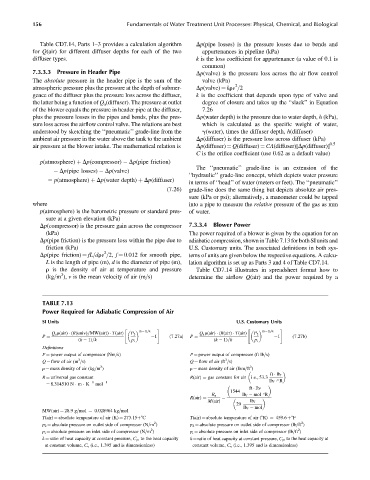
TABLE 7.13
Power Required for Adiabatic Compression of Air
SI Units U.S. Customary Units
" (k 1)=k # " (k 1)=k #
Q a r(air) (R(univ)=MW(air)) T(air) P 2 Q a r(air) (R(air) T(air) P 2
1 (7:27a) 1 (7:27b)
P ¼ P ¼
(k 1)=k p i (k 1)=k p i
Definitions
P ¼ power output of compressor (Nm=s) P ¼ power output of compressor (ft lb=s)
3
3
Q ¼ flow of air (m =s) Q ¼ flow of air (ft =s)
3
3
r ¼ mass density of air (kg=m ) r ¼ mass density of air (lbm=ft )
ft lb f
R ¼ universal gas constant R(air) ¼ gas constant for air i:e:,53:3
¼ 8.314510 N m K 1 mol 1 lb f R
ft lb f
1544
R u lb f mol R
R(air) ¼ ¼
M(air) lb f
29
lb f mol
MW(air) ¼ 28.9 g=mol ¼ 0.028964 kg=mol
T(air) ¼ absolute temperature of air (K) ¼ 273.15þ8C T(air) ¼ absolute temperature of air (8R) ¼ 459.6 þ8F
2
2
p 2 ¼ absolute pressure on outlet side of compressor (N=m ) p 2 ¼ absolute pressure on outlet side of compressor (lb=ft )
2
2
p i ¼ absolute pressure on inlet side of compressor (N=m ) p i ¼ absolute pressure on inlet side of compressor (lb=ft )
k ¼ ratio of heat capacity at constant pressure, C p , to the heat capacity k ¼ ratio of heat capacity at constant pressure, C p , to the heat capacity at
at constant volume, C v (i.e., 1.395 and is dimensionless) constant volume, C v (i.e., 1.395 and is dimensionless)