
Page 199 - Fundamentals of Water Treatment Unit Processes : Physical, Chemical, and Biological
P. 199
154 Fundamentals of Water Treatment Unit Processes: Physical, Chemical, and Biological
Determine airflow: Select coarse bubble diffuser because Concerning airflow, 4.6 Q(air-per-unit-length) 12.4
3
it is less likely to clog and will require less maintenance. L=s=m of length, or 3 Q(air-per-unit-length) 8ft =min=ft
(ASCE-WPCF, 1977, p. 137). The range for Q(air-for-basin)
Q(air, coarse bubble, v H ¼ 0:2m=s) calculates as
¼ [0:07 þ 0:76 ln d(air header)] 1:33
Q(air-for-basin-min) ¼ Q(air-per-unit-length) L(basin)
¼ [0:07 þ 0:76 ln 2:00] 1:33
¼ (4:6L=s=m of length) 46 m
3
3
¼ 2:00 N m =m h
¼ 212 L air=s
3
2
3
Q(air-for-basin) ¼ (2:00 N m =m h) (8:0m 46 m) 3
¼ 3:5Nm air=min
3
¼ 736 N m =h
3
3
¼ 12:3Nm =min The range is thus 3.5 Q(air-for-basin) 9.5 N m air=min,
which is less than the value calculated based on the
3
(Note, the N in front of m means ‘‘normal’’ temperature Londong (1989) equation.
and pressure, that is, 208C, 1.0 atm pressure.)
Alternate criteria: Morales and Reinhart (1984) give
7.3.3 PRACTICE:AERATED GRIT CHAMBERS
u ¼ 2 5 min
Guidelines for aerated grit chamber practice are sparse, and
d(particles removed) 0.21 mm
most designs rely on empirical rules-of-thumb. This section
R(0.21 mm particles) 95% reviews one paper that illustrates the diversity found in oper-
ating plant designs.
These criteria are based upon a study of empirical data
without regard to rationale. The detention time recom- 7.3.3.1 Guidelines from Five Designs
mended by Londong, that is, about 20 min, is much longer
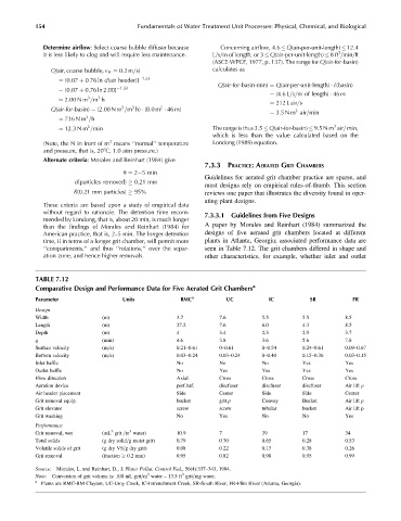
than the findings of Morales and Reinhart (1984) for A paper by Morales and Reinhart (1984) summarized the
American practice, that is, 2–5 min. The longer detention designs of five aerated grit chambers located at different
time, if in terms of a longer grit chamber, will permit more plants in Atlanta, Georgia; associated performance data are
‘‘compartments,’’ and thus ‘‘rotations,’’ over the separ- seen in Table 7.12. The grit chambers differed in shape and
ation zone, and hence higher removals. other characteristics, for example, whether inlet and outlet
TABLE 7.12
Comparative Design and Performance Data for Five Aerated Grit Chambers a
Parameter Units RMC a UC IC SR FR
Design
Width (m) 3.7 7.6 5.5 5.5 8.5
Length (m) 27.2 7.6 6.0 4.3 8.5
Depth (m) 4 3.4 2.3 2.9 3.7
q (min) 4.6 3.8 3.6 5.6 7.8
Surface velocity (m=s) 0.21–0.61 0–0.61 0–0.54 0.24–0.61 0.09–0.67
Bottom velocity (m=s) 0.03–0.24 0.03–0.24 0–0.40 0.15–0.36 0.03–0.15
Inlet baffle No No No Yes Yes
Outlet baffle No Yes Yes Yes Yes
Flow direction Axial Cross Cross Cross Cross
Aeration device perf.baf. discfuser discfuser discfuser Air lift p
Air header placement Side Center Side Side Center
Grit removal equip. bucket grit p Convey Bucket Air lift p
Grit elevator screw screw tubular bucket Air lift p
Grit washing No Yes No No Yes
Performance
3 3
Grit removal, wet (mL grit =m water) 10.9 7 39 17 34
Total solids (g dry solid=g moist grit) 0.79 0.70 0.65 0.28 0.53
Volatile solids of grit (g dry VS=g dry grit) 0.08 0.22 0.13 0.38 0.26
Grit removal (fraction 0.2 mm) 0.95 0.82 0.98 0.95 0.99
Source: Morales, L. and Reinhart, D., J. Water Pollut. Control Fed., 56(4):337–343, 1984.
3
3
Note: Conversion of grit volume is: 100 mL grit=m water ¼ 13.5 ft grit=mg water.
a
Plants are RMC-RM Clayton, UC-Utoy Creek, IC-Intrenchment Creek, SR-South River, FR-Flint River (Atlanta, Georgia).