
Page 195 - Fundamentals of Water Treatment Unit Processes : Physical, Chemical, and Biological
P. 195
150 Fundamentals of Water Treatment Unit Processes: Physical, Chemical, and Biological
7.3.2 THEORY OF AERATED GRIT CHAMBERS
TABLE 7.10
Figure 7.14 shows the velocity vectors of a grit particle in
Sieve Analysis of Particles Collected in Grit Chambers
the separation zone, that is, the velocity, v T , of the circula-
Sieve
Percentage Retained tion, and the settling velocity, v S .The resultantvelocity is
Sieve Size Open
v R . Particles that enter the separation zone will be removed
(U.S. Series) (mm) Green Bay Kenosha Tampa St. Paul
if the resultant velocity vector, v R , intersects the bottom,
4 4.76 1–7 that is, the top plane of the grit collector. Each rotation
8 2.38 5–20 provides another ‘‘pass’’ across the separation zone, and
10 2.08 3.7 12 thus the opportunity for further settling to the collection
20 0.84 9.1 2–53 zone. A third vector, v H , transports the particle in direction
40 0.42 19.8 70 of the flow, that is, normal to the plane of the paper. Thus,
50 0.30 29.6 2.3 20–67 v R (particle) ¼ v S þ v H þ v T . The particle is transported with
65 0.21 51.7
the flow but with the settling velocity vector, v S , superim-
80 0.18 95
posedonthe fluid motion.
100 0.15 78.2 59.3 97–99.9
200 0.07 96.1 99.5
7.3.2.1 Calculation of Grit Removal
Source: Adapted from ASCE-WPCF, ASCE Manual of Engineering
Figure 7.15 illustrates the spiral path of the circulation for a
Practice No. 36 and the WPCF Manual of Practice No. 8,
section of the grit chamber with length, DL. Particles that start
American Society of Civil Engineers, New York, 1959.
at a point A will be advanced to point B over one rotation.
During each ‘‘rotation’’ of the water mass with entrained
grit particles, a fraction, P, of the grit will enter the ‘‘separ-
(1.0 ft=s). Also, as with horizontal flow grit chambers, the goal ation zone’’ and will be removed. After the ‘‘pass,’’ the
is to remove grit particles, d(grit) 0.2 mm, for SG 2.65 turbulence will redistribute the remaining grit particles. Dur-
with organic-mass-fraction 0.05. ing the next pass, the same fraction, P, of remaining particles
will be removed. To illustrate, suppose P ¼ 0.2 and let the
suspension contain 10 particles at point A of Figure 7.15.
7.3.1 PRINCIPLES OF AERATED GRIT CHAMBER OPERATION
Then two that is of the particles will be removed and eight
Theoretically, the fraction of grit removed is proportional to particles will remain in suspension at point B and circulated
the number of ‘‘rolls,’’ which favors a long-narrow shape, that again, with the same proportion of particles removed over the
is, with more ‘‘rolls’’ per unit length. second ‘‘pass.’’
6
7
5
1 2 3
4
Influent
8
10
9
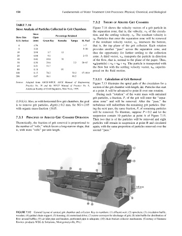
FIGURE 7.12 General layout of aerated grit chamber and collector. Key to numbers: (1) effluent weir; (2) sprockets; (3) circulation baffle,
wooden; (4) guided chain support; (5) housing; (6) motorized drive; (7) screw conveyor for discharge of grit; (8) inlet baffle for distribution of
flow around baffles; (9) air inlet pipe and headers, perforated pipe is adequate; (10) chain bucket collector mechanism. (Courtesy of Siemens
Envirex products WSG & Solutions, Montgomeryville, PA.)