
Page 192 - Fundamentals of Water Treatment Unit Processes : Physical, Chemical, and Biological
P. 192
Grit Chambers 147
TABLE CD7.7
Calculated Parabolic Grit Chamber Section for Selected Parshall Flume
Parshall Flume Parabolic Grit Chamber Section
Q
Flume H a v H y p X A(parab) v H
2
3
(mgd) (m =s) (m) C n (m) (m=s) (m) (m) (m) (m ) (m=s)
(a) Selection of Parshall flume
0.453 0.305 0.69 1.52 0.758
(b) Determination of p for parabolic grit chamber section
1.00 0.044 0.305 0.69 1.52 0.163 0.305 0.163 0.6693
(c) Calculation of H a , x, A(parab), and verification of v H for grit chamber
0.00 0 0 0.000 0.000 0.000 0
0.20 0.0088 0.0566 0.057 0.389 0.029 0.299
0.50 0.0219 0.1033 0.103 0.526 0.072 0.302
1.00 0.0438 0.163 0.163 0.661 0.144 0.305
2.00 0.0876 0.2572 0.257 0.830 0.285 0.308
3.00 0.1314 0.3359 0.336 0.948 0.425 0.309
4.00 0.1752 0.4059 0.406 1.042 0.564 0.311
6.00 0.2628 0.53 0.530 1.191 0.842 0.312
7.00 0.3067 0.5865 0.587 1.253 0.980 0.313
8.00 0.3505 0.6404 0.640 1.309 1.118 0.313
10.00 0.4381 0.7416 0.742 1.409 1.393 0.314
0.8
0.7
0.6
0.5
y (m) 0.4
0.3
0.2
0.1
0.0
0.0 0.2 0.4 0.6 0.8 1.0 1.2 1.4 1.6
x (m)
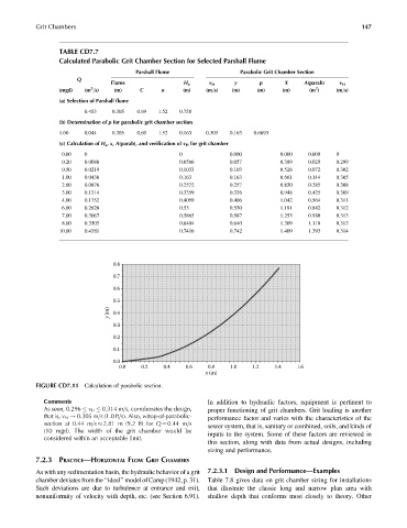
FIGURE CD7.11 Calculation of parabolic section.
Comments In addition to hydraulic factors, equipment is pertinent to
As seen, 0.296 v H 0.314 m=s, corroborates the design, proper functioning of grit chambers. Grit loading is another
that is, v H ! 0.305 m=s (1.0 ft=s). Also, w(top-of-parabolic- performance factor and varies with the characteristics of the
section at 0.44 m=s 2.81 m (9.2 ft) for Q ¼ 0.44 m=s
sewer system, that is, sanitary or combined, soils, and kinds of
(10 mgd). The width of the grit chamber would be
inputs to the system. Some of these factors are reviewed in
considered within an acceptable limit.
this section, along with data from actual designs, including
sizing and performance.
7.2.3 PRACTICE—HORIZONTAL FLOW GRIT CHAMBERS
As with any sedimentation basin, the hydraulic behavior of a grit 7.2.3.1 Design and Performance—Examples
chamber deviates from the ‘‘ideal’’ model of Camp (1942, p. 31). Table 7.8 gives data on grit chamber sizing for installations
Such deviations are due to turbulence at entrance and exit, that illustrate the classic long and narrow plan area with
nonuniformity of velocity with depth, etc. (see Section 6.91). shallow depth that conforms most closely to theory. Other