
Page 193 - Fundamentals of Water Treatment Unit Processes : Physical, Chemical, and Biological
P. 193
148 Fundamentals of Water Treatment Unit Processes: Physical, Chemical, and Biological
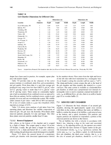
TABLE 7.8
Grit Chamber Dimensions for Different Cities
Dimensions (m) Dimensions (ft)
No.
Location Channels Depth Length Width Depth Length Width
South Milwaukee, WI 1 0.99 12.95 1.22 3.25 42.50 4.00
Ephrata, WA 1 0.76 7.62 0.91 2.50 25.00 3.00
Vicksburg, MS 1 1.22 14.33 1.52 4.00 47.00 5.00
Watertown, NY 2 1.22 6.10 0.48 4.00 20.00 1.58
Toledo, OH 2 1.52 13.41 1.22 5.00 44.00 4.00
Portsmouth, VA 3 1.45 17.60 1.83 4.75 57.75 6.00
Oswego, NY 1 0.30 6.00 0.51 1.00 19.67 1.67
Mt. Pleasant, IA 1 0.91 10.67 0.91 3.00 35.00 3.00
Freeport, IL 2 1.30 13.72 1.22 4.25 45.00 4.00
Salisbury, NC 2 0.76 12.19 1.22 2.50 40.00 4.00
Libertyville, IL 1 1.07 9.14 0.76 3.50 30.00 2.50
Waukesha, WI 1 1.30 16.25 1.62 4.25 53.33 5.33
Roxboro, NC 1 0.86 11.28 1.37 2.83 37.00 4.50
Meriden, CT 2 0.59 12.19 1.98 1.92 40.00 6.50
South Cobb County, GA 2 1.68 9.75 1.22 5.50 32.00 4.00
Brigantine, NJ 1 0.46 6.10 0.91 1.50 20.00 3.00
Eufala, OK 1 0.43 5.18 0.61 1.42 17.00 2.00
Portsmouth, VA 3 1.45 18.90 1.83 4.75 62.00 6.00
Middlesex, NJ 1 1.98 12.22 1.37 6.50 40.08 4.50
Bordentown, NJ 1 1.07 10.67 0.76 3.50 35.00 2.50
Source: Adapted from Rexnord, Grit chambers data sheet, in: Rexnord Product Manual, Rexnord, Inc., Waukesha, WI, 1980.
shapes have been used in practice, for example, square plan by the numbers shown. Flow enters from the right and leaves
area with shallow depth. on the left side with level maintained by a rectangular weir.
Table 7.9 provides data on the character of the sewer An air header is along the concrete wall (to cause a ‘‘roll’’).
system (sanitary or combined), plant flow, grit accumulation, The chain-and-bucket system scrapes the grit to the head of
and grit quality. From these data it is seen that average grit the grit chamber and then transfers the material to a screw
3
production may range from less than 0.0075 L grit=m water conveyor. The same system is available as a horizontal-flow
3
3
(1.0 ft grit=mg water) to more than 0.15 L grit=m water grit chamber, in which case a proportional weir (instead of a
3
(20 ft grit=mg water). There seems no consistently higher rectangular weir) is used to maintain constant horizontal vel-
rate of grit accumulation from combined sewers as opposed to ocity, v H , at different flows, Q; also, there is no airflow header
those that are sanitary, but for combined sewers, surges in grit pipe (9) or wooden baffle (3).
quantity do occur and can overwhelm the system. The volatile
solids content of grit varies—with 20% to 50% not unusual;
7.3 AERATED GRIT CHAMBERS
5% or less of volatile solids is a goal. Rex Chainbelt (1965)
reported an average of 8.5%. Figure 7.13 illustrates the basic elements of an aerated grit
Table 7.10 shows sieve analyses of grit taken from four chamber, showing the approximately square cross section
operating plants and illustrates the variable composition of with fillets in the corners, a diffuser that emits air bubbles, a
removed grit. On grit sizes the Kenosha (Wisconsin) plant baffle to confine the stream of air bubbles, a grit removal zone
removed particles primarily 0.2 mm and larger. The other at the bottom, and a spiral circulation. Grit particles and
three plants removed particles smaller than 0.2 mm. organic particles are depicted as suspended; a portion of the
removed particles are shown at the bottom.
7.2.3.2 Removal Equipment The air bubbles rise with a velocity in accordance with
Grit collects on the bottom of the chamber and is scraped Stoke’s law, inducing a drag on the water and associated
by a flight of blades. The scraper speed is about 3.0 m=min velocity, v T . By adjusting airflow, Q a , the operator can control
(10 ft=min). Usually, the grit enters a hopper for collection; v T , and thus the mass fraction of organic matter in the grit.
removal is by a chain-and-bucket lift or a screw conveyor. The horizontal velocity, v H ,is v H ¼ Q=A(cross section); the
Afterwashing,thegrit drops into a truck fortransport to a landfill. vector sum, v H þ v T ¼ v R ,defines a spiral. As with horizontal
Figure 7.12 shows the general layout of a proprietary flow grit chambers, the ideal scour velocity, that is, v T in
aerated grit chamber with associated appurtenances labeled the case of aerated grit chambers, should be v T 0.3 m=s