
Page 190 - Fundamentals of Water Treatment Unit Processes : Physical, Chemical, and Biological
P. 190
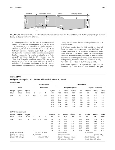
Grit Chambers                                                                                    145


                            Transition    Converging section  Throat        Diverging section

                                                                                             h L
                            0.75 m  (2.40 ft)  H   0.67 m  (2.19 ft)                         0.44 m  (1.44 ft)

                                            a
                                                                 H b
                                    ΔZ=0.08 m (0.21 ft)


            FIGURE 7.10  Installation of 0.61 m (24 in.) Parshall flume to operate under free-flow conditions, with 2.74 m (9.0 ft) wide grit chamber,
                                3
            flowing at Q(max) ¼ 0.76 m =s (27.0 cfs).
              4. Submergence limit: For the 0.61 m (24 in.) Parshall  Q may be calculated for the submerged condition if it
              flume, the transition submergence is S t ¼ 0.66 (Table  is not excessive.
              7.3), where H b =H a ¼ S t . Therefore, at Q(max), H b (max) ¼  5. Hydraulic profile: For the 0.61 m (24 in.) Parshall
              H a (max)   S t ¼ 0.67 m   0.66 ¼ 0.44 m (1.44 ft). If the  flume, the transition submergence, S t ¼ 0.66 (Table 7.3),
              tailwater elevation increases such that H b ¼ H b (max),  permits calculation of the maximum downstream water
              the hydraulic condition is called transition-submergence.  depth, which is H a ¼ 0.44 m (1.44 ft). The tailwater depth
              Further increase in H b results, eventually, in a ‘‘sub-  should be maintained lower, however, in order to ensure
              merged’’ condition, that is, H a increases and the  a certainty that submergence will not occur. As a note, the
              ‘‘free-flow’’ hydraulic condition ceases. This means that
                                                                  corresponding headloss across the flume is h L ¼ H a
              measurement of H a is no longer sufficient, by itself, to  H b ¼ 0.67   0.44 ¼ 0.23 m (0.75 ft) (Figure 7.10).
              calculate Q. For proper functioning of the grit chamber
              the free-flow condition should be maintained, although  Spreadsheet algorithm: A spreadsheet algorithm, as
                                                                  illustrated by Table CD7.6, can facilitate the grit


            TABLE CD7.6
            Design of Rectangular Grit Chamber with Parshall Flume as Control
            (a) Metric units
                                           Parshall Flume                          Grit Chamber
                    Flows                   Coefficients              Design for Q(max)         Depth, v for Q(min)
            Q(avg)  Q(max)  Q(min)                    H a (max)  w   v(max)  d(max)  DZ     H a (min)  d(min)  v(min)
                      3
                              3
              3
            (m =s)  (m =s)  (m =s)   C     n     S t    (m)    (m)   (m=s)    (m)    (m)     (m)     (m)    (m=s)
            0.44     0.66    0.22   1.06  1.54  0.64   0.73    2.13   0.30   1.01     0.28   0.36    0.64    0.16
                                                       0.73    2.13   0.38   0.81     0.08   0.36    0.43    0.24
                                                       0.73    2.44   0.30   0.88     0.15   0.36    0.51    0.18
                                                       0.73    2.44   0.37   0.74     0.00   0.36    0.36    0.25
                                                       0.73    2.74   0.30   0.79     0.05   0.36    0.41    0.19
                                                       0.73    2.74   0.34   0.71    0.02    0.36    0.34    0.23

            (b) U.S. Customary units
            Q(avg)  Q(max)  Q(min)                   H a (max)  w   v(max)  d(max)   DZ    H a (min)  d(min)  v(min)
             3
                      3
                              3
            (ft =s)  (ft =s)  (ft =s)  C   n    S t    (ft)    (ft)  (ft=s)  (ft)    (ft)    (ft)    (ft)   (ft=s)
            15.47   23.21    7.74   6.00  1.54  0.64   2.41   7.00   1.00    3.32    0.91   1.18     2.09   0.53
                                                       2.41   7.00   1.25    2.65    0.25   1.18     1.42   0.78
                                                       2.41   8.00   1.00    2.90    0.49   1.18     1.67   0.58
                                                       2.41   8.00   1.20    2.42    0.01   1.18     1.19   0.81
                                                       2.41   9.00   1.00    2.58    0.17   1.18     1.35   0.64
                                                       2.41   9.00   1.10    2.34    0.06   1.18     1.12   0.77
            Q(avg) was assumed      C, n, S t for 18 in. flume  w was assumed               H a calculated:
            Q(max) ¼ 1.5   Q(avg)   H a calculated:           v(max) was assumed                    Q( min )¼CH a  n
            Q(min) ¼ 0.5   Q(avg)         Q( max )¼CH a n     d(max) ¼ Q(max)=w   v(max)   d(min) ¼ H a (min) þ DZ
                                                              DZ ¼ d(max)   H a (max)      v(min) ¼ Q(min)=b   d(min)