
Page 185 - Fundamentals of Water Treatment Unit Processes : Physical, Chemical, and Biological
P. 185
140 Fundamentals of Water Treatment Unit Processes: Physical, Chemical, and Biological
TABLE CD7.3
Free Flow Ranges, Coefficients, and Exponents for Parshall Flumes of Various Throat Widths a
3
3
Q (ft =s) Q (m =s) w t b C
Min Max Min Max U.S. Cust. Metric (m) U.S. Cust. Metric n S t c
0.01 0.02 0.00028 0.00057 1 in. 0.0254 0.338 0.0605 1.55 0.56
0.02 0.4 0.00057 0.0113 2 in. 0.051 0.676 0.085 1.55 0.61
0.03 0.6 0.00085 0.017 3 in. 0.076 0.992 0.178 1.55 0.64
0.05 2.9 0.0014 0.0821 6 in. 0.152 2.06 0.382 1.58 0.55
0.1 5.1 0.00283 0.1444 9 in. 0.229 3.07 0.536 1.53 0.63
0.4 16 0.0113 0.4531 12 in. 0.305 4.00 0.69 1.52 0.62
0.5 24 0.0142 0.6797 18 in. 0.457 6.00 1.06 1.54 0.64
0.7 33 0.0198 0.9346 24 in. 0.61 8.00 1.43 1.55 0.66
0.8 41 0.0227 1.1611 30 in. 0.762 10.00 1.80 1.555 0.67
1.00 50 0.0283 1.416 3.0 ft 0.914 12.00 2.17 1.56 0.68
1.3 68 0.0368 1.9258 4.0 ft 1.219 16.00 2.93 1.57 0.70
2.2 86 0.0623 2.435 5.0 ft 1.524 20.00 3.70 1.58 0.72
2.6 104 0.0736 2.945 6.0 ft 1.829 24.00 4.50 1.59 0.74
4.1 121 0.116 3.427 7.0 ft 2.134 28.00 5.32 1.60 0.76
4.6 140 0.130 3.965 8.0 ft 2.438 32.00 6.08 1.60 0.78
6.0 200 0.170 5.664 10.0 ft 3.048 40.13 7.52 1.59 0.8
Source: Adapted from Skogerboe, G.V. et al., Parshall Flumes, Report WG31-3, OWRR Project No. B-006-Utah, Utah Water Research Laboratory, Utah
State University, Logan, UT, March, 1967.
a
Metric units were calculated from Skogerboe et al. (1967) data in this table.
b
Throat width of flume.
c
S t is called the ‘‘transition submergence’’; the condition occurs approximately when H b =H a > S t .
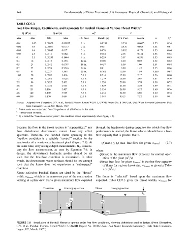
Because the flow in the throat section is ‘‘supercritical,’’ any through the headworks during operation for which free-flow
flow disturbance downstream cannot have any effect performance is desired, the flume selected should have a free-
upstream. Therefore, the Parshall flume operating in the flow capacity that is greater, that is,
free-flow condition is a suitable ‘‘control’’ section for the
headworks of a wastewater treatment plant (Figure 7.8). At Q( max ) Q( max free flow for given w throat ) (7:7)
the same time, only a single depth measurement, H a , is neces-
sary for flow measurement, as seen by Equation 7.6. In where
design, the downstream hydraulic profile should be set Q(max) is the maximum flow expected for normal oper-
such that the free-flow condition is maintained. In other ation of the plant (m =s)
3
words, the downstream water surfaces should be low enough Q(max free flow for given w throat ) is the free-flow capacity
such that the flume does not experience a ‘‘submerged’’ of flume for a given throat size, w throat , as given in Table
condition. 7.3 (m =s)
3
Flume selection: Parshall flumes are sized by the ‘‘throat’’
width, w throat , which is the narrowest part of the construction The flume is ‘‘selected’’ based upon the maximum flow
looking at a plan view. For a given maximum flow expected expected. Table CD7.3 gives the throat widths, w throat , for
Transition Converging section Throat Diverging section
h L
H a
d H b
H a
ΔZ H b
FIGURE 7.8 Installation of Parshall Flume to operate under free-flow conditions, showing definitions used in design. (From Skogerboe,
G.V. et al., Parshall Flumes, Report WG31-3, OWRR Project No. B-006-Utah, Utah Water Research Laboratory, Utah State University,
Logan, UT, March, 1967.)