
Page 186 - Fundamentals of Water Treatment Unit Processes : Physical, Chemical, and Biological
P. 186
Grit Chambers 141
different maximum flows, along with the associated coeffi- H b that can be tolerated before the onset of the submerged-
cients, C and n, and the S t criteria. Example 7.2 illustrates a flow condition. If H b (measured) H b (calculated), then the
selection of flume size. submerged condition exists.
Example 7.2 Selection of Parshall Flume
Example 7.3 Determination of Maximum Level
Problem statement of H b for Incipient Submergence
3
3
Select a flume for a flow, Q(max) ¼ 0.35 m =s (12.36 ft =s
or 8.0 mgd). Problem
For a 305 mm (12 in.) Parshall flume, determine the max-
Solution
imum level of H b , that is, H b (max) for the maximum-flow
Referring to Table CD7.3, a flume with w throat ¼ 0.305 m
3
(12 in.) has a ‘‘free-flow’’ capacity, Q(max) ¼ 0.45 m =s condition, Q(max).
3
(16 ft =s). The associated coefficients are: C ¼ 0.69 in SI Solution
3
units (4.00 in. for ft and s units) and n ¼ 1.52. Extract from Table 7.3 the row for the 305 mm flume, as
shown in Table CD7.4a. Set up Table CD7.4b to calcu-
Discussion
The next larger flume size, that is, w throat ¼ 0.457 m late H a (max) by Equation 7.6 and from this result, cal-
3
3
(18 in), has a capacity, Q(max) ¼ 0.68 m =s (24 ft =s), culate H b (max) by Equation 7.8. The result was
which is more than required. Also depth differences for H b (max) ¼ 470 mm.
the flow variation would be appreciably less. Therefore, Discussion
the selection should be w throat ¼ 0.305 m (12 in.). If the tailwater level should rise such that H b H b (max),
then submerged conditions will occur. If Q has lesser
Submerged flow: Submerged flow is caused by a downstream value, the same procedure is followed, that is, H a is cal-
backup of the flow such that the super-critical velocity in the culated by Equation 7.6, and H b is calculated by Equation
throat of the flume no longer exists. The S t values in Table 7.3 7.8. If the tailwater level rises to cause a larger value of H b
are the criteria, for respective throat widths, that determine the than is calculated by Equation 7.8, then the submerged
point of transition to the ‘‘submerged’’ flow condition. When condition will occur.
H b =H a ¼ S t the flow begins to become ‘‘unstable’’ and as the
ratio H b =H a increases, that is, H b =H a > S t , the submerged-flow Construction data: The Parshall flume must be constructed
condition becomes established.
in accordance with certain dimensions for each throat size,
Hydraulic profile: The important question for a Parshall flume is w throat . Figure 7.9 designates the dimensions for any Parshall
the maximum level of H b for which incipient submergence flume. The dimensions for each flume size are given in Table
occurs. This can be determined by the relation CD7.5a and b for metric and U.S. Customary units, respect-
ively. As seen in Figure 7.9, the converging flow section is
H b
¼ S t (7:8) level. The throat section has a downward slope (where
H a
H=E ¼ 9=24) and then an upward slope (where (H K)=
where S t is the maximum ratio of H b =H a for incipient submer- F ¼ 1=26). Parshall flumes up to a certain size may be
gence from Table 7.3. prefabricated and installed in a prepared channel. Proprietary
For a given Q, H a may be calculated by Equation 7.6 and prefabricated units are available up to a certain sizes. For
then H b from Equation 7.8. The latter is the maximum level of units constructed in place, concrete is used (commonly).
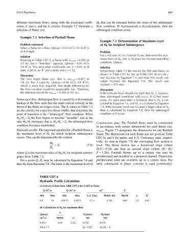
TABLE CD7.4
Hydraulic Profile Calculation
(a) Extract of data from Table CD7.3 for 0.305 m flume
3
3
Q (ft =s) Q (m =s) w t b C
Min Max Min Max U.S. Cust. Metric (m) Metric n S t c
0.4 16 0.0113 0.4531 12 in. 0.305 0.69 1.52 0.62
(b) Calculation of H b for maximum flow
C
Q(max) H a (max) H b (max)
3
(m =s) Metric n (m) (m)
0.4531 0.69 1.52 0.758 0.470
n
Table 7.3 Q ¼ CH a H b =H a ¼ S t