Page 184 - Fundamentals of Water Treatment Unit Processes : Physical, Chemical, and Biological
P. 184

Grit Chambers                                                                                    139


                  0.70                                         in bulletins of the CSU Agricultural Experiment Station and the
                                                               U.S. Department of Agriculture. The report of Skogerboe et al.
                  0.60                                         (1967) was the first systematic calibration of the Parshall flume
                                                               coefficients since the original work of Parshall in the late 1920s
                                                               and the early 1930s and was used as the primary reference for
                  0.50
                                                               this section.
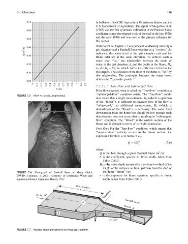
                                                               Water level tie: Figure 7.7 is a perspective drawing showing a
                  0.40
                 Q (m 3 /s)                                    grit chamber and a Parshall flume together as a ‘‘system.’’ As
                                                               indicated, the water level at the grit chamber exit and the
                  0.30
                                                               flume inlet are at the same elevation. To achieve such a
                                                               water level ‘‘tie,’’ the relationship between the depth of
                  0.20                                         water in the grit chamber, d, and the depth in the flume, H a ,
                                                               is, d ¼ H a þ DZ, in which DZ is the difference between the
                  0.10                                         two depths. The elevation of the floor of the flume is ‘‘set’’ by
                                                               this relationship. The continuity between the water levels
                                                               defines the ‘‘hydraulic profile.’’
                  0.00
                          0.1  0.2  0.3  0.4  0.5  0.6  0.7  0.8  0.9  1.1  1.2  7.2.2.2.1  Free Flow and Submerged Flow
                       0                           1
                                     h (m)
                                                               If the flow exceeds, what is called the ‘‘free-flow’’ condition, a
                                                               ‘‘submerged-flow’’ condition exists. The ‘‘free-flow’’ condi-
            FIGURE 7.5 Flow vs. depth, proportional.
                                                               tion means that a single measurement, H a (which is upstream
                                                               of the ‘‘throat’’), is sufficient to measure flow. If the flow is
                                                               ‘‘submerged,’’ an additional measurement, H b (which is
                                                               downstream of the ‘‘throat’’), is necessary. The water level
                                                               downstream from the flume box should be low enough such
                                                               that a backup does not occur, that is, resulting in ‘‘submerged-
                                                               flow’’ condition. The ‘‘throat’’ is the narrow section of the
                                                               flume and is defined in terms of its width dimension.
                                                               Free flow: For the ‘‘free-flow’’ condition, which means that
                                                               ‘‘super-critical’’ velocity occurs in the throat section, the
                                                               expression for flow is in terms of H a ,

                                                                                    Q ¼ CH n                (7:6)
                                                                                           a
                                                               where
                                                                                                        3
                                                                  Q is the flow through a given Parshall flume (m =s)
                                                                  C is the coefficient, specific to throat width, taken from
                                                                    Table CD7.3
                                                                  H a is the water depth measured at a section two-third of the
                                                                    length of the entrance section upstream from the start of
            FIGURE 7.6 Photograph of Parshall flume at Marcy Gulch   the flume ‘‘throat’’ (m)
            WWTP, Colorado, c. 2003. (Courtesy of Centennial Water and  n is the exponent for flume equation, specific to throat
            Sanitation District, Highlands Ranch, CO.)              width, taken from Table CD7.3


                                                  Grit chamber
                                                     L
                                                                    Transition
                        Q = v ·wd
                            H
                                                       w                          Parshall flume
                                                                                 Throat
                                                                                       w t
                                      d
                                                                     H a
                                                              ΔZ
                                                                            n
                                                                       Q = CH a
            FIGURE 7.7 Parshall flume perspective showing grit chamber.
   179   180   181   182   183   184   185   186   187   188   189