
Page 187 - Fundamentals of Water Treatment Unit Processes : Physical, Chemical, and Biological
P. 187
142 Fundamentals of Water Treatment Unit Processes: Physical, Chemical, and Biological
D E F
H a
H
2/3 C b
A W B
C
Top view
Converging inlet section Throat section Diverging outlet section
G Q
K
H a
H b
Side view H
Y
X
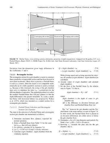
FIGURE 7.9 Parshall flume, views defining sections, dimensions, and points of depth measurement. (Adapted from Skogerboe, G.V. et al.,
Parshall Flumes, Report WG31-3, OWRR Project No. B-006-Utah, Utah Water Research Laboratory, Utah State University, Logan, UT,
March, 1967.)
Deviations from the dimensions given imply differences in Q ¼ A(grit chamber) v H (7:9)
the coefficients, C and n. ¼ [w(grit chamber) d(grit chamber)] v H (7:10)
7.2.2.3 Rectangular Section
With Q being stated and v H being specified by criter-
The rectangular section for a grit chamber is easier to construct ion, the product [w(grit chamber) d(grit chamber)] is
than a parabolic or trapezoidal section and has been favored in calculated.
most plant headworks. Most often in practice a Parshall flume 6. Assume values of w(grit chamber) and calculate
is used as a control, albeit the match is not compatible math- d(grit chamber).
ematically (as it is with a parabolic section) to yield a constant 7. Set the floor of the Parshall flume by the relation
v H . Because of this mismatch, the sizing of the grit chamber seen in Figure 7.8, that is,
must serve to minimize the term [v H v H (criterion)] for the
different depths of operation. The general procedure is to select d(grit chamber) ¼ H a þ DZ (7:11)
the smallest Parshall flume that will pass Q(max) so that the
depth differential is the greatest attainable. As a note, a modi- where
fied flume with horizontal bottom was proposed by Walker d(grit chamber) is the depth of water in grit
et al. (1973), which was intended as a control section for a chamber (m)
rectangular grit chamber. DZ is the difference in elevation between grit
chamber floor and Parshall flume floor (m)
7.2.2.3.1 Parshall Flume Selection and Rectangular
Section Grit Chamber The ‘‘tie’’ between the grit chamber and the Par-
shall flume is the water surface, as seen in Figure 7.8.
The steps in the selection of a Parshall flume and a rectangular
In other words, the Parshall flume floor is placed at
section grit chamber are enumerated as follows:
an elevation differential, DZ, either above or below
the grit chamber floor.
1. Determine maximum flow, Q(max), expected for
8. Determine v o for a 0.2 mm diameter sand particle (by
normal operation.
Stoke’s law, v o (SG ¼ 2.65) 30 mm=s).
2. Select a Parshall flume from Table 7.3 for the smal-
9. Knowing v o , calculate the plan area for the grit
lest w throat that will pass Q(max).
chamber, that is,
3. For Q(max), calculate H a by Equation 7.6.
4. Let v H ¼ 0.305 m=s (Camp’s velocity criterion).
5. Calculate w(grit chamber) d(grit chamber) from the Q ¼ A(plan) v o (7:12)
continuity equation. ¼ [w(grit chamber) L(grit chamber)] v o (7:13)