
Page 198 - Fundamentals of Water Treatment Unit Processes : Physical, Chemical, and Biological
P. 198
Grit Chambers 153
For calculation, set up a spreadsheet or refer to Table
TABLE 7.11 CD7.14 for airflow calculations.
Criteria for Design of Aerated Grit Chamber Determine sizing: Criteria in Table 7.11 will be applied to
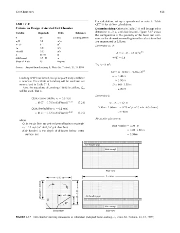
determine w, D, L, and d(air header). Figure 7.17 shows
Variable Magnitude Units Reference
the configuration of the geometry of the basin and sum-
u 20 min Londong (1989) marizes the dimensions resulting from the calculations that
w=D 0.8 m=m are enumerated as follows:
w D 1–7 m 2
Determine w, D:
v H 0.20 m=s
v(axial) 0.10 m=s 0:5
A ¼ w D 0:5(w=2)
L 15–60 m
d(diffusers) 0.7 D m w=D ¼ 0:8
Slope of fillets 45 Degrees
2
Try A ¼ 8m :
Source: Adapted from Londong, J., Water Sci. Technol., 21, 13, 1989.
8:0 ¼ w (0:8w) 0:5(w=2) 0:5
w ¼ 3:44 m
Londong (1989) are based on a pilot plant study and have
a rationale. The criteria of Londong will be used and are 3:50 m
summarized in Table 7.11. D ¼ 0:8 3:50 m
Also, the equations of Londong (1989) for airflow, Q a , ¼ 2:80 m
will be used, that is,
Determine L:
Q(air, coarse bubble, v T ¼ 0:2m=s)
¼ [0:07 þ 0:76 ln d(diffuser)] 1:33 (7:24) w D L ¼ Q u
2
3:50 m 2:80 m L ¼ 0:75 m =s (10 min 60 s= min )
Q(air, fine bubble, v T ¼ 0:2m=s)
¼ [0:63 þ 0:52 ln d(diffuser)] 0:62 (7:25) L 46 m
Air header placement:
where
Q a is the air flow per unit volume of basin to maintain
3
3
v T ¼ 0.2 m=s(m air=h=m grit chamber) d(air header) ¼ 0:70 D
d(air header) is the depth of diffusers below water ¼ 0:70 2:80 m
surface (m) ¼ 2:00 m
Air header pipe
Grit trough
Plan view
L =46 m
w = 3.50 m
d(header) = 2.00 m w/2 D = 2.80 m
w/2 Air header pipe
45°
Grit trough
Front view Side view
FIGURE 7.17 Grit chamber showing dimensions as calculated. (Adapted from Londong, J., Water Sci. Technol., 21, 13, 1989.)