
Page 202 - Fundamentals of Water Treatment Unit Processes : Physical, Chemical, and Biological
P. 202
Grit Chambers 157
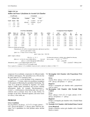
TABLE CD7.14
Airflow and Power Calculations for Aerated Grit Chamber
1 Coefficients 2 Constants
Diffuser Type Constant Value Units
Coeff. Coarse Fine R ¼ 8.314510 J K mol 1
1
0.028964 kg=mol
0.07 0.63 MW(air) ¼
a ¼
1.395
0.76 0.52 k ¼
b ¼
1.33 0.62
c ¼
3 Air Flow Calculations 4 Compressor Power Required
d(diff) Q(air, co) Q(air, f ) V(Gr Ch) Q(air) Elev. p(atm) T r(air) r(air) p 2 P
3
3
3
3
3
3
(m) (m =m=h) (m =m=h) (m ) (m =s) (m) (Pa) 8C (mol=m ) (kg=m ) (Pa) (kW) (hp)
0.90 >1000 1.409 375 0.1 0 101325 20 41.57 1.204 303975 21 27.5
1.00 34.357 1.332 375 0.1 0 101325 20 41.57 1.204 303975 19 25.9
1.50 3.645 1.113 375 0.1 0 101325 20 41.57 1.204 303975 16 21.7
2.00 1.987 1.006 375 0.1 0 101325 20 41.57 1.204 303975 15 19.6
2.50 1.425 0.939 375 0.1 0 101325 20 41.57 1.204 303975 14 18.3
3.00 1.142 0.893 375 0.1 0 101325 20 41.57 1.204 303975 13 17.4
5 Notes on columns and equations
3
Dimensions are m air flow (at normal temperature and pressure) per hour Assumed Diffuser p þ Dp(losses)
3
per m of grit chamber volume
c
Q(air) ¼ [a þ b ln(d)] (from Londong, 1989)
Q(air) ¼ Q(air, fine) V(Gr Ch)
d(diff) ¼ depth of diffuser
V(Gr Ch) ¼ w D L Use barometric pressure or default value adjusted for elevation,
Q(air, co) ¼ air flow for coarse bubble diffuser Assumed that is, p(atm) ¼ 101,325 * 10 0.00005456*Z
Q(air, f) ¼ air flow through fine bubble diffuser r(air) ¼ p(atm)=RT
3
3
Alternatively, Q(air) ¼ 3–8ft =min=ft length (ASCE, 1977) r(air) ¼ p(mol=m ) * MW(air)=1000
3
¼ 0.0046–0.0124 m =s=m length of tank
Power required by compressor is for an adiabatic compression and is calculated by relations in Table 7.13
compressor for an adiabatic compression for different depths 7.1 Rectangular Grit Chamber with Proportional Weir
of diffuser submergence. The spreadsheet (on a CD) also has Control
the same table in U.S. Customary units. Given
The pressure, p 2 , on the discharge of the compressor was 3
Assume flows: Q(avg) ¼ 0.22 m =s (5 mgd), Q(min) ¼
assumed as p 2 ¼ 3 p(atm), which was an arbitrary assumption 0.30 Q(avg), and Q(max) ¼ 3 Q(avg).
for the purpose of illustrating the spreadsheet functioning. The
Required
value of p 2 should be calculated by Equation 7.26, which
Design a rectangular grit chamber with a proportional
requires another linked spreadsheet and involves utilizing
weir as control.
7.2 Rectangular Grit Chamber with Parshall Flume
submergence depth, for example, Dp(submergence) ¼
r(water) g z(submergence), determining pipe sizes, and cal-
Control
culations such as pressure losses due to pipe friction, for
example, by the Darcy–Weisbach equation, and minor losses Given
3
for valves, a flow meter, etc. Flows: Q(avg) ¼ 0.22 m =s (5 mgd), Q(min) ¼ 0.30
Q(avg), and Q(max) ¼ 3 Q(avg).
Required
PROBLEMS Design a rectangular grit chamber with a Parshall flume
as control.
Given Conditions
3 7.3 Parabolic Grit Chamber with Parshall Flume Control
For all problems, let Q(avg) ¼ 0.22 m =s (5 mgd), Q(min) ¼
0.30 Q(avg) and Q(max) ¼ 3 Q(avg), unless otherwise spe- Given=Required
cified. Use a spreadsheet for each problem unless advised Design a parabolic section grit chamber with a Parshall
otherwise. flume as control.