
Page 375 - Fundamentals of Water Treatment Unit Processes : Physical, Chemical, and Biological
P. 375
330 Fundamentals of Water Treatment Unit Processes: Physical, Chemical, and Biological
wash and=or an air scour; one or both is essential to cleaning
Filter tank
Wash troughs the media adequately. The wastewater from the backwash is
removed by overflow launders, that is, troughs. After the
backwash is completed, the filtration cycle is started again.
Provision for filter-to-waste is recommended, which may be
Filter used during the filter ‘‘ripening,’’ that is, at the start of the
media filter run.
The system also includes provision for treated water stor-
age, both to provide detention time for disinfection and to
account for diurnal fluctuation in demand, and perhaps help
Graded meet days of peak demand. Backwash water may be stored
gravel
separately and elevated, which avoids the risk of a cross
connection with treated water storage. The wastewater is
Perforated laterals
conveyed to a solids storage pond where the decanted water
Filter floor
is returned to the head of the plant.
Cast-iron manifold
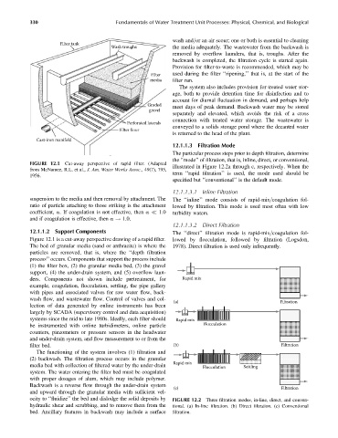
12.1.1.3 Filtration Mode
The particular process steps prior to depth filtration, determine
the ‘‘mode’’ of filtration, that is, inline, direct, or conventional,
FIGURE 12.1 Cut-away perspective of rapid filter. (Adapted
illustrated in Figure 12.2a through c, respectively. When the
from McNamee, R.L. et al., J. Am. Water Works Assoc., 49(7), 795,
term ‘‘rapid filtration’’ is used, the mode used should be
1956.
specified but ‘‘conventional’’ is the default mode.
12.1.1.3.1 Inline Filtration
suspension to the media and then removal by attachment. The The ‘‘inline’’ mode consists of rapid-mix=coagulation fol-
ratio of particle attaching to those striking is the attachment lowed by filtration. This mode is used most often with low
coefficient, a. If coagulation is not effective, then a 1.0 turbidity waters.
and if coagulation is effective, then a ! 1.0.
12.1.1.3.2 Direct Filtration
12.1.1.2 Support Components The ‘‘direct’’ filtration mode is rapid-mix=coagulation fol-
Figure 12.1 is a cut-away perspective drawing of a rapid filter. lowed by flocculation, followed by filtration (Logsdon,
The bed of granular media (sand or anthracite) is where the 1978). Direct filtration is used only infrequently.
particles are removed, that is, where the ‘‘depth filtration
process’’ occurs. Components that support the process include
(1) the filter box, (2) the granular media bed, (3) the gravel
support, (4) the under-drain system, and (5) overflow laun-
ders. Components not shown include pretreatment, for Rapid mix
example, coagulation, flocculation, settling, the pipe gallery
with pipes and associated valves for raw water flow, back-
wash flow, and wastewater flow. Control of valves and col-
(a) Filtration
lection of data generated by online instruments has been
largely by SCADA (supervisory control and data acquisition)
systems since the mid to late 1980s. Ideally, each filter should Rapid mix
be instrumented with online turbidimeters, online particle Flocculation
counters, piezometers or pressure sensors in the headwater
and under-drain system, and flow measurement to or from the
filter bed. (b) Filtration
The functioning of the system involves (1) filtration and
(2) backwash. The filtration process occurs in the granular
Rapid mix
media bed with collection of filtered water by the under-drain Flocculation Settling
system. The water entering the filter bed must be coagulated
with proper dosages of alum, which may include polymer.
Backwash is a reverse flow through the under-drain system
(c) Filtration
and upward through the granular media with sufficient vel-
ocity to ‘‘fluidize’’ the bed and dislodge the solid deposits by FIGURE 12.2 Three filtration modes, in-line, direct, and conven-
hydraulic shear and scrubbing, and to remove them from the tional. (a) In-line filtration. (b) Direct filtration. (c) Conventional
bed. Ancillary features in backwash may include a surface filtration.