
Page 440 - Fundamentals of Water Treatment Unit Processes : Physical, Chemical, and Biological
P. 440
13 Slow Sand Filtration
As a ‘‘process,’’ slow sand might be classified as ‘‘biofiltra- 13.1.1.3 Schmutzdecke
tion.’’ It has its own identity as a ‘‘technology’’ and a ‘‘practice’’ A characteristic of slow sand is the formation of a surface
that is reviewed here briefly, along with theory (Box 13.1). deposit called the schmutzdecke, a German word meaning
‘‘sludge blanket,’’ or ‘‘dirty layer,’’ both apt terms for the
13.1 DESCRIPTION phenomenon observed, also illustrated in Figure 13.1. As
the schmutzdecke develops, whether by deposit of material
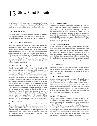
A slow sand filter is merely a bed ofsand, confined within a box, or growth of organisms, or both, the headloss increases. A
with appurtenances to deliver and remove water. Figure 13.1 major task of the operation is to remove the schmutzdecke (see
illustrates the main elements of the process and technology. Section 12.2.1.1) when the headloss exceeds some established
criterion, usually 2.0 m (6 ft).
13.1.1 SLOW SAND TECHNOLOGY
13.1.1.4 Design Approach
Slow sand consists of a filter box with appurtenances that
To make the process work, design guidelines should be fol-
measure and control flows for the operation, for example,
lowed and appurtenances must be added. The design goal is to
inflow, filtered water drainage, backfilling after scraping,
provide passive operation. In other words, the design engineer
headwater drainage, etc. All of this is to support a biological
must endeavor to ensure that proper plant operation will be
depth-filtration process, which is within the sand bed, coupled
self-evident and self-implementing to the operator through the
with a straining process, by a layer of material deposited, and
life of the filter. If the design engineer achieves this goal, then
perhaps with organism growth. The straining occurs on top of
slow sand filtration can be an appropriate technology for small
the sand bed, called the schmutzdecke. Slow sand filtration
communities, where operators may have other responsibilities.
may be characterized as a passive process in that it occurs
without operator intervention.
13.1.2 ATTRIBUTES
13.1.1.1 Filter Box and Appurtenances
Slow sand is effective as a process and is economical in
Usually, the sand bed is 1.0–1.2 m (3–4 ft), but there is no rigid
certain contexts, especially for small communities. Being
rule. As seen in Figure 13.1, the sand bed is supported by a
simple in design and construction and passive in operation
graded gravel support, usually 0.3 m (1.0 ft), contained within a
adds to its appeal.
concrete ‘‘box.’’ On the floor of the box, and within the gravel
support, are the underdrains to remove the filtered water. The
13.1.2.1 Selection Criteria
filtered water then enters the tailwater whose elevation is con-
Preferred source water turbidity levels are <10 nephelometric
trolled by a weir plate on the effluent side of the filter. The flow
turbidity units (NTU). As an upper limit, 30–50 NTU has
of raw water to the filter is controlled by a valve on the influent
side, with flow meter preceding. The energy of the incoming been mentioned as a rule of thumb, but the limit is more a
matter of engineering and judgment than an absolute level.
raw water must be dissipated so that the sand bed is not eroded,
Factors include: effluent turbidity, length of run, and whether
which would cause higher local velocity through the sand bed.
pretreatment may be acceptable. Color and volatile organics
In other words, the energy of the portion of the diffusion cone
are other considerations; if the raw water concentrations are
(illustrated in Figure 13.1) as it intercepts the surface of the
high, then a pilot plant study may be advisable.
sand bed should not be sufficient to lift the sand grains. This
can be done by providing about 300–600 mm (12–24 in.)
13.1.2.2 Effectiveness
minimum depth of water at the start of the filter run as a ‘‘rule
of thumb,’’ and by distributing the flow around the filter box. The slow sand filtration process is expected to remove bio-
logical particles such as cysts, oocysts, algae, bacteria, viruses,
13.1.1.2 Sand Bed parasite eggs, nematode eggs, and amorphous organic debris at
The sand bed must be biologically ‘‘mature’’ to be effective in 2-log to 4-log levels when the filter bed is biologically mature
filtration. This means that the sand grains must have devel- (or ‘‘ripened’’). The foregoing applies to biological particles
oped a biological film, that is, a community of microorgan- present in the influent flow. There are other organisms that may
isms adhering to their surfaces, to which particles in the find ecological niches within the schmutzdecke or within the
ambient water may ‘‘stick’’ once a collision occurs. The filter bed. Those organisms that adhere to the sand grains
removal mechanism is ‘‘depth-filtration’’ (described in Sec- within the filter bed comprise the biofilm that gives the sand
tions 12.3 and 13.2.1.2). bed ‘‘maturity’’ (also called a ‘‘ripened’’ sand bed).
395