
Page 444 - Fundamentals of Water Treatment Unit Processes : Physical, Chemical, and Biological
P. 444
Slow Sand Filtration 399
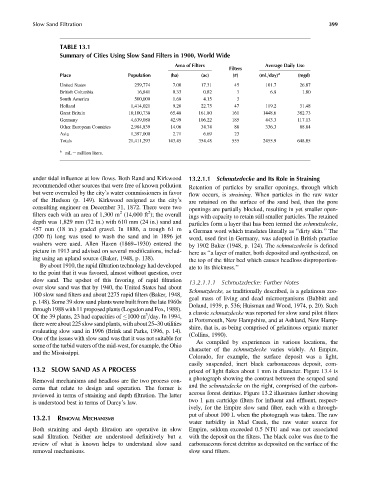
TABLE 13.1
Summary of Cities Using Slow Sand Filters in 1900, World Wide
Area of Filters Average Daily Use
Filters
Place Population (ha) (ac) (#) (mL=day) a (mgd)
United States 259,774 7.00 17.31 45 101.7 26.87
British Columbia 16,841 0.33 0.82 3 6.8 1.80
South America 500,000 1.68 4.15 3
Holland 1,414,021 9.20 22.75 47 119.2 31.48
Great Britain 10,100,738 65.48 161.80 161 1448.6 382.73
Germany 4,639,080 42.99 106.22 185 443.3 117.13
Other European Countries 2,984,839 14.06 34.74 88 336.3 88.84
Asia 1,397,000 2.71 6.69 23
Totals 21,411,293 143.45 354.48 555 2455.9 648.85
a
mL ¼ million liters.
under tidal influence at low flows. Both Rand and Kirkwood 13.2.1.1 Schmutzdecke and Its Role in Straining
recommended other sources that were free of known pollution Retention of particles by smaller openings, through which
but were overruled by the city’s water commissioners in favor flow occurs, is straining. When particles in the raw water
of the Hudson (p. 149). Kirkwood resigned as the city’s are retained on the surface of the sand bed, then the pore
consulting engineer on December 31, 1872. There were two openings are partially blocked, resulting in yet smaller open-
2
2
filters each with an area of 1,300 m (14,000 ft ); the overall ings with capacity to retain still smaller particles. The retained
depth was 1,829 mm (72 in.) with 610 mm (24 in.) sand and particles form a layer that has been termed the schmutzdecke,
457 mm (18 in.) graded gravel. In 1886, a trough 61 m a German word which translates literally as ‘‘dirty skin.’’ The
(200 ft) long was used to wash the sand and in 1896 jet word, used first in Germany, was adopted in British practice
washers were used. Allen Hazen (1869–1930) entered the by 1902 Baker (1948, p. 124). The schmutzedecke is defined
picture in 1913 and advised on several modifications, includ- here as ‘‘a layer of matter, both deposited and synthesized, on
ing using an upland source (Baker, 1948, p. 138). the top of the filter bed which causes headloss disproportion-
By about 1910, the rapid filtration technology had developed ate to its thickness.’’
to the point that it was favored, almost without question, over
slow sand. The upshot of this favoring of rapid filtration
13.2.1.1.1 Schmutzdecke: Further Notes
over slow sand was that by 1940, the United States had about
Schmutzdecke, as traditionally described, is a gelatinous zoo-
100 slow sand filters and about 2275 rapid filters (Baker, 1948,
geal mass of living and dead microorganisms (Babbitt and
p. 148). Some 39 slow sand plants were built from the late 1960s
Doland, 1939, p. 536; Huisman and Wood, 1974, p. 20). Such
through 1988 with 11 proposed plants (Logsdon and Fox, 1988). a classic schmutzdecke was reported for slow sand pilot filters
3
Of the 39 plants, 23 had capacities of 1000 m =day. In 1994,
at Portsmouth, New Hampshire, and at Ashland, New Hamp-
there were about 225 slow sand plants, with about 25–30 utilities
shire, that is, as being comprised of gelatinous organic matter
evaluating slow sand in 1996 (Brink and Parks, 1996, p. 14).
(Collins, 1990).
One of the issues with slow sand was that it was not suitable for
As compiled by experiences in various locations, the
some of the turbid waters of the mid-west, for example, the Ohio
character of the schmutzdecke varies widely. At Empire,
and the Mississippi.
Colorado, for example, the surface deposit was a light,
easily suspended, inert black carbonaceous deposit, com-
13.2 SLOW SAND AS A PROCESS prised of light flakes about 1 mm in diameter. Figure 13.4 is
a photograph showing the contrast between the scraped sand
Removal mechanisms and headloss are the two process con-
and the schmutzdecke on the right, comprised of the carbon-
cerns that relate to design and operation. The former is
aceous forest detritus. Figure 13.2 illustrates further showing
reviewed in terms of straining and depth filtration. The latter
two 1 mm cartridge filters for influent and effluent, respect-
is understood best in terms of Darcy’s law.
ively, for the Empire slow sand filter, each with a through-
put of about 100 L when the photograph was taken. The raw
13.2.1 REMOVAL MECHANISMS
water turbidity in Mad Creek, the raw water source for
Both straining and depth filtration are operative in slow Empire, seldom exceeded 0.5 NTU and was not associated
sand filtration. Neither are understood definitively but a with the deposit on the filters. The black color was due to the
review of what is known helps to understand slow sand carbonaceous forest detritus as deposited on the surface of the
removal mechanisms. slow sand filters.