
Page 447 - Fundamentals of Water Treatment Unit Processes : Physical, Chemical, and Biological
P. 447
402 Fundamentals of Water Treatment Unit Processes: Physical, Chemical, and Biological
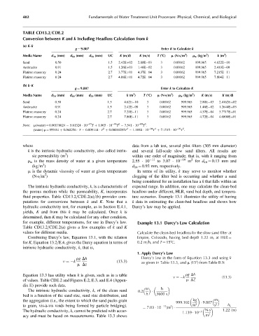
TABLE CD13.2=CDE.2
Conversion between K and k Including Headloss Calculation from k
(a) K–k
g ¼ 9.807 Enter K to Calculate k
2
3
2
Media Name d 10 (mm) d 60 (mm) d 50 (mm) UC K (m=d) K (m=s) T (8C) m (N-s=m ) r w (kg=m ) k (m )
Sand 0.50 1.5 2.42Eþ02 2.80E 03 3 0.00162 999.965 4.622E 10
Anthracite 0.91 1.5 1.26Eþ03 1.46E 02 3 0.00162 999.965 2.419E 09
Flatiron masonry 0.24 2.7 3.77Eþ01 4.37E 04 3 0.00162 999.965 7.215E 11
Flatiron masonry 0.24 2.7 4.08Eþ01 4.72E 04 3 0.00162 999.965 7.804E 11
(b) k–K
g ¼ 9.807 Enter k to Calculate K
2
3
2
Media Name d 10 (mm) d 60 (mm) d 50 (mm) UC k (m ) T (8C) m (N-s=m ) r w (kg=m ) K (m=s) K (m=d)
Sand 0.50 1.5 4.62E 10 3 0.00162 999.965 2.80E 03 2.4162Eþ02
Anthracite 0.91 1.5 2.42E 09 3 0.00162 999.965 1.46E 02 1.2644Eþ03
Flatiron masonry 0.24 2.7 7.21E 11 3 0.00162 999.965 4.37E 04 3.7717Eþ01
Flatiron masonry 0.24 2.7 7.80E 11 3 0.00162 999.965 4.72E 04 4.0800Eþ01
T .
T 7.541 10
Note: m(water) ¼ 0.00178024 5.61324 10 05 T þ 1.003 10 06 2 09 3
3
2
(water) r ¼ 999.84 þ 0.068256 T 0.009144 T þ 0.00010295T 1.1888 10 06 4 09 5
T .
T þ 7.1515 10
where data from a lab test, several pilot filters (305 mm diameter)
k is the intrinsic hydraulic conductivity, also called intrin- and several full-scale slow sand filters. All results are
2
sic permeability (m ) within one order of magnitude, that is, with k ranging from
2
r w is the mass density of water at a given temperature 2.55 10 11 to 3.07 10 10 m for d 10 ¼ 0.13 mm and
3
(kg=m ) d 10 ¼ 0.92 mm, respectively.
m is the dynamic viscosity of water at given temperature In terms of its utility, k may serve to monitor whether
2
(N-s=m ) clogging of the filter bed is occurring and whether a sand
being considered for an installation has a k that falls within an
The intrinsic hydraulic conductivity, k, is a characteristic of expected range. In addition, one may calculate the clean-bed
the porous medium while the permeability, K, incorporates headloss under different, HLR, sand bed depth, and tempera-
fluid properties. Table CD13.2=CDE.2(a)=(b) provides com- ture scenarios. Example 13.1 illustrates the utility of having
putations for conversions between k and K. Note that a k data in estimating the clean-bed headloss and shows how
hydraulic conductivity test, for example, as in Section E.4.1, Darcy’s law may be applied.
yields, K and from this k may be calculated. Once k is
determined, then K may be calculated for any other condition,
for example, different temperatures, for use in Darcy’s law. Example 13.1 Darcy’s Law Calculation
Table CD13.2=CDE.2(a) gives a few examples of k and K
values for different media. Calculate the clean-bed headloss for the slow sand filter at
Combining Darcy’s law, Equation 13.1, with the relation Empire, Colorado, having bed depth 1.22 m, at HLR ¼
for K, Equation 13.2=E.4, gives the Darcy equation in terms of 0.2 m=h, and T ¼ 158C.
intrinsic hydraulic conductivity, k, that is,
1. Apply Darcy’s Law
rg Dh Darcy’s law in the form of Equation 13.3 and using k
v ¼ k (13:3) as given in Table 13.3, and m (158) from Table B.9:
m Dz
Equation 13.3 has utility when k is given, such as in a table rg Dh
v ¼ k (13:3)
of values. Table CDE.2 and Figures E.2, E.3, and E.4 (Appen- m DZ
dix E) provide such data.
m
h
The intrinsic hydraulic conductivity, k, of the clean sand 0:2
bed is a function of the sand size, sand size distribution, and h 3600 s
the aggregation (i.e., the extent to which the sand packs grain kg m
999:102 3 9:807 2
to grain, vis-à-vis voids being formed by particle bridging). ¼ 7:03 10 11 (m ) m s h L
2
The hydraulic conductivity, k, cannot be predicted with accur- 1:139 10 3 N-s 1:22 (m)
acy and must be based on measurements. Table 13.3 shows m 2