
Page 451 - Fundamentals of Water Treatment Unit Processes : Physical, Chemical, and Biological
P. 451
406 Fundamentals of Water Treatment Unit Processes: Physical, Chemical, and Biological
Pre-cast concrete roof slab where
2
0.3 p is the pressure at depth h (Pa) or (lb=ft )
h is the depth below water surface (m) or (ft)
3
g w is the specific weight of water (9990 N=m ) or (62.4
3
Headwater lb=ft )
2.0–3.0 The force on a wall due to the hydraulic pressure is calcu-
lated by applying the concept of the pressure prism:
F ¼ (g h=2) A(wall) (13:5)
w
1.0–1.5 Sand where
F is the force on wall (N or lb)
2
2
A(wall) is the area of wall (m or ft )
Gravel Example 13.3 illustrates the application of the foregoing
0.6 Underdrain equation.
(Measurements in meters) Example 13.3 Pressure and Force
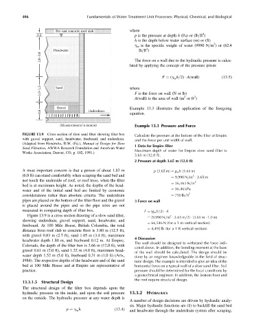
FIGURE 13.9 Cross section of slow sand filter showing filter box Calculate the pressure at the bottom of the filter at Empire
with gravel support, sand, headwater, freeboard, and underdrain. and the force per unit width of wall.
(Adapted from Hendricks, D.W. (Ed.), Manual of Design for Slow
1 Data for Empire filter
Sand Filtration, AWWA Research Foundation and American Water
Works Association, Denver, CO, p. 102, 1991.) Maximum depth of water for Empire slow sand filter is
3.65 m (12.0 ft).
2 Pressure at depth 3.65 m (12.0 ft)
A most important concern is that a person of about 1.83 m p (3:65 m) ¼ g w h (3:65 m)
(6.0 ft) can stand comfortably when scraping the sand bed and 3
¼ 9,990 N=m 3:65 m
not touch the underside of roof, or roof truss, when the filter 2
¼ 36,463 N=m
bed is at maximum height. As noted, the depths of the head-
water and of the initial sand bed are limited by economic ¼ 36:46 kPa
2
considerations rather than absolute criteria. The underdrain ¼ 750 lb=ft
pipes are placed on the bottom of the filter floor and the gravel 3 Force on wall
is placed around the pipes and so the pipe sizes are not
measured in computing depth of filter box. F ¼ (g w h=2) A
Figure 13.9 is a cross section drawing of a slow sand filter, 2
¼ (9,990 N=m 3:65 m=2) (3:65 m 1:0m)
showing underdrain, gravel support, sand, headwater, and
¼ 66,546 N (for a 1 m vertical section)
freeboard. At 100 Mile House, British Columbia, the total
¼ 4,492 lb (for a 1 ft vertical section)
distance from roof slab to concrete floor is 3.80 m (12.5 ft),
with gravel 0.83 m (2.7 ft), sand 1.05 m (3.4 ft), maximum
4 Discussion
headwater depth 1.80 m, and freeboard 0.12 m. At Empire,
The wall should be designed to withstand the force indi-
Colorado, the depth of the filter box is 3.66 m (12.0 ft), with
cated above. In addition, the bending moment at the base
gravel 0.61 m (2.0 ft), sand 1.22 m (4.0 ft), maximum head-
of the wall should be calculated. The design should be
water depth 1.52 m (5.0 ft), freeboard 0.31 m (1.0 ft) (Arix,
done by an engineer knowledgeable in the field of struc-
1984). The respective depths of the headwater and of the sand tural design. The example is intended to give an idea of the
bed at 100 Mile House and at Empire are representative of horizontal force on a typical wall of a slow sand filter. Soil
practice. pressure should be determined for the local conditions by
a geotechnical engineer. In addition, the bottom floor and
the roof require structural design.
13.3.1.5 Structural Design
The structural design of the filter box depends upon the
hydraulic pressure on the inside, and upon the soil pressure 13.3.2 HYDRAULICS
on the outside. The hydraulic pressure at any water depth is
A number of design decisions are driven by hydraulic analy-
sis. Major hydraulic functions are (1) to backfill the sand bed
p ¼ g h (13:4) and headwater through the underdrain system after scraping;
w