
Page 455 - Fundamentals of Water Treatment Unit Processes : Physical, Chemical, and Biological
P. 455
410 Fundamentals of Water Treatment Unit Processes: Physical, Chemical, and Biological
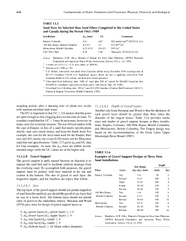
TABLE 13.5
Sand Sizes for Selected Slow Sand Filters Completed in the United States
and Canada during the Period 1965–1989
Installation d 10 (mm) UC Comments
a,b
Empire, Colorado 0.21 2.67 $21=metric ton ($19=U.S. ton)
c,d
100 Mile House, British Columbia 0.2–0.3 3.3 $11.60 =m 3
e
Moricetown, British Columbia 0.15–0.35 2.0–2.5 $34 =m 3
CSU Pilot Plant 0.28 1.46 Muscatine: $128=metric ton
Source: Hendricks, D.W. (Ed.), Manual of Design for Slow Sand Filtration, AWWA Research
Foundation and American Water Works Association, Denver, CO, p. 117, 1991.
a
1 metric ton (mT) ¼ 1.1 U.S. tons (short, or 2000 lb).
b
Seelaus et al. (1986, p. 38).
c
U.S. dollars; conversion was made from Canadian dollars using December 1984 exchange rate of
$0.7577 Canadian ¼ $1.00 U.S. Significant figures shown are due to applying conversion from
Canadian dollars to U.S. dollars, and does not connote precision.
d 3 3
Calculated from following data: 1000 m sand plus 560 m gravel for $24,000 Canadian plus
$10,000 for installation (personal communication, Jack Bryck, Sept. 20, 1990).
e 3
Calculated from following data: 250 m sand $11,250 Canadian (Contract Bid Document 168.21.2,
Dayton & Knight, Vancouver, British Columbia, 1988).
sampling period, after a ripening time of about two weeks 13.3.2.8.2 Depth of Gravel Layers
with nutrient-enriched feed water. Another rule from Huisman and Wood is that the thickness of
The UC is important in that UC 2.0 ensures that the pores each gravel layer should be greater than three times the
are open enough so that clogging does not become an issue. To diameter of the largest stones. Table 13.6 provides media
consider a sand that has UC > 3 may be necessary, however, in sizes and depths of gravel support designs at three installa-
many cases for economic reasons. The use of local sand as with tions: Empire, Colorado; 100 Mile House, British Columbia;
the case at Empire, in lieu of a sand that meets specifications and Moricetown, British Columbia. The Empire design was
strictly, may save much money and keep the funds local. For based on the recommendations of the Great Lakes Upper
example, the cost for the local sand used for the Empire filter Mississippi River Board (1987).
was only $21=metric ton versus $128=metric ton for Muscatine
sand that met specifications. Table 13.5 gives d 10 and UC data
for four examples. As seen, the d 10 sizes are within recom-
mended range while the UC values are at the higher end.
TABLE 13.6
13.3.2.8 Gravel Support Examples of Gravel Support Designs at Three Slow
The gravel support is aptly named because its function is to Sand Installations
support the sand bed and to facilitate uniform drainage from Depth
the overlying sand. To accomplish both purposes, the gravel Size Range
Place Layer (d 10 –d 90 ) (mm) (mm) (in.)
support must be graded, with finer material at the top and
coarser at the bottom. The size of gravel in each layer, the Empire, Colorado Top 3–6 50 2
respective depths, and the headloss are topics that follow. Second 6–13 100 4
Third 13.19 100 4
13.3.2.8.1 Size Fourth 19–38 130 5
The top layer of the gravel support should not permit migration Bottom 38–64 230 9
of sand from the sand bed, nor should the gravel of any layer find 100 Mile House, Top 3–6 150 6
British Columbia Second 9–14 150 6
its way to a lower level. The bottom layer should not permit
Bottom 20–63 300 12
entry of gravel to the underdrain orifices. Huisman and Wood
Moricetown, Top 2.5–3 150 6
(1974) gave rules for design of gravel support layers as
British Columbia Second 10–15 150 6
Bottom 40–60 300 12
1. d 90 (given layer)=d 10 (given layer) 1.4
2. d 10 (lower layer)=d 10 (upper layer) 4 Source: Hendricks, D.W. (Ed.), Manual of Design for Slow Sand Filtration,
3. d 10 (top layer)=d 15 (sand) 4 AWWA Research Foundation and American Water Works
4. d 10 (top layer)=d 85 (sand) 4 Association, Denver, CO, p. 13, 1991.
5. d 10 (bottom layer) 2d (drain orifice diameter)