
Page 458 - Fundamentals of Water Treatment Unit Processes : Physical, Chemical, and Biological
P. 458
Slow Sand Filtration 413
(a)
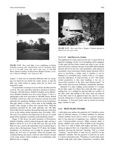
FIGURE 13.19 Slow sand filter at Empire, Colorado adjacent to
Mad Creek, raw water source.
13.3.3.12 Sand Recovery System
The arguments for onsite sand recovery are (1) sand will be at
(b)
hand for resanding; (2) the cost of resanding will be minimal;
(3) the sand will have been washed and ready to use; (4) the
FIGURE 13.18 Slow sand filters at two installations in British
sand will not be a nuisance because of possible indiscriminate
Columbia showing earth embankments used for insulation; about
0.3 m (1 ft) earth covers slab roof in each case. (a) 100 Mile discard; and (5) in any new sand acquisition, some degree of
House, British Columbia, (b) Moricetown, British Columbia. (Cour- uncertainty exists concerning whether proper attention will be
tesy of Dayton & Knight, Ltd., Vancouver, BC.) given to specifying a proper sand or whether it can be
obtained at a reasonable price. Jordan (1920, p. 13) empha-
sized the importance of sand recovery, to wit: ‘‘The funda-
sloped 1:2; there was no structural difficulty with ice. Scrap-
mental proposition is that sand handling is the key to
ing was timed for just before the winter season, so that the
(successful) operation of the slow sand filtration plant.’’ In
filter run could extend to spring when the ice block was
other words, sand recovery facilitates a sustainable operation.
expected to melt.
Elements of a sand washing system include (1) a storage
To prevent the occurrence of an ice block, the filter must be
bin for dirty sand; (2) a flume that carries the dirty sand to a
covered. The slow sand filters placed in operation at Empire,
settling box; (3) a settling box that provides for overflow of
Colorado; 100 Mile House, British Columbia; and at Morice-
the dirty water and settling of the clean sand; (4) removal
town, British Columbia were all covered. Figure 13.18a is a
of the dirty water to an approved land site; and (5) a sluice
photograph of the slow sand filter at 100 Mile House, British
from the settling box to a bin for washed sand, which provides
Columbia, which has a flat roof of precast concrete and earth
for drainage. A front-end loader may be useful for moving
sidewalls; the operations building is shown in the foreground.
large volumes of sand.
The pipe gallery is below a floor grate in the building and
treated water storage is below the concrete floor. With the
insulation provided by the earth sidewalls, the 100 Mile 13.4 PILOT PLANT STUDIES
House filter had no auxiliary heat and has had only a thin skin
of ice on the surface during operation since November, 1985. A pilot plant may address the questions of (1) headloss versus
The lack of ice problem was helped also by the use of a small time for different seasons, (2) effluent turbidity for different
pump which maintains circulation at the headwater surface. influent turbidity levels (due to storms or seasonal changes),
Figure 13.18b shows the earth insulation at Moricetown, and (3) log removals of organisms (e.g., coliforms, Giardia
British Columbia, which is placed along the sides and has a cysts, Cryptosporidium oocysts). Other concerns relate to
depth of about 0.3 m (1 ft) on the slab roof. The top of the design variables such as the effect of HLR on the foregoing,
filter box has a port to the operations room to permit heat to the effect of a shift in HLR, both higher and lower, due to
advect above the headwater. Figure 13.19 shows the Empire taking an adjacent filter out of operation or being returned to
installation; ice formation was avoided by propane heaters operation, the time for sand bed ‘‘ripening,’’ that is, to reach
during the first years of operation. When the propane was ‘‘maturity,’’ and the effect of sand size (d 10 and UC) on the
exhausted during one season, a thin ice cake formed over part dependent variables. The first question is sufficient, by itself,
of the water surface which resulted in an inordinately more to warrant a pilot plant study. The phases of a pilot plant study
difficult task in scraping. include study plan, pilot plant construction, execution, data