
Page 460 - Fundamentals of Water Treatment Unit Processes : Physical, Chemical, and Biological
P. 460
Slow Sand Filtration 415
The 100 mm diameter PVC drainpipe was perforated in the the spot, keeping expenses low and without the need to wait
portion that drained the bottom gravel layer, and the bend for supplies. Second, local persons were trained to obtain the
served as a weir with a 20–30 mm (1 in.) hole drilled in the needed measurements of headwater elevation and turbidity.
top of the bend to ensure an air break for the tailwater Third, the pilot plant study was simple, with limited scope,
control. The headwater level was measured by a scale designed to answer only the critical questions of run time and
attached to the inside wall above the sand bed and to the effluent turbidity. Fourth, the duration of the study was only 4
top of the pipe. A drain valve was attached to the lower part months and included the most adverse raw water quality
of the effluent pipe to drain the column. This type of pilot condition, that is, algae growth.
plant setup is easy to construct, and is inexpensive since it
uses materials at hand.
13.5 OPERATION
13.4.2.3 Results
A major appeal of slow sand filtration is its simplicity in
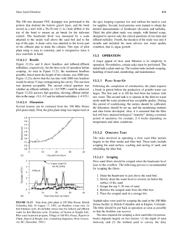
Figure 13.21a and b show headloss and influent=effluent operation. Nevertheless, certain tasks must be performed. The
turbidities, respectively, for the first cycle of operation before initial task is plant start-up. The routine tasks include scraping,
scraping. As seen in Figure 13.21, the maximum headloss handling of used sand, monitoring, and maintenance.
possible, based upon the height of the column, was 2000 mm.
Figure 13.21a shows that the run time with 2000 mm headloss
would be about 33 days (extrapolating the curve). This run time 13.5.1 PLANT START-UP
was deemed acceptable. The second critical question was Following the completion of construction, the plant requires
whether an effluent turbidity of <0.5 NTU could be achieved. a break in period before the production of potable water can
Figure 13.21b answers that question, showing effluent turbid- begin. The first task is to fill the bed from the bottom with
ities in the range <0.1–0.5 and for influent turbidities 1–4 NTU. raw water. The second task is to operate in the filter-to-waste
mode until the water produced has acceptable quality. During
13.4.2.4 Discussion
this period of conditioning, the meters should be calibrated,
Several lessons can be extracted from the 100 Mile House
the laboratory should be set up, and the monitoring routines
pilot plant study. First, the pilot plant setup was improvised on
and data forms developed. Also, it is assumed that the filter
bed will have attained biological ‘‘maturity’’ during a nominal
1.8 period of operation, for example, 2–4 weeks depending on
1.6 temperature and other conditions.
1.4
Headloss (m) 1.0 13.5.2 OPERATING TASKS
1.2
0.8
0.6
largely to the filter media and filter bed. These tasks include
0.4 The tasks involved in operating a slow sand filter pertain
0.2 scraping the sand surface, washing and storing of sand, and
0.0 rebuilding the filter bed.
0 10 20 30 40
(a) Elapsed time (days)
13.5.2.1 Scraping
5 Slow sand filters should be scraped when the headwater level
Upper limit US
4 Influent for SS (1990) rises to the overflow. The following process is recommended
Turbidity (NTU) 3 1. Drain the headwater to just above the sand bed.
for scraping the filters:
2
2. Slowly drain the water level to several cm below the
1 surface of the sand.
Effluent 3. Scrape the top 5–30 mm of sand.
0 4. Remove the scraped sand from the filter box.
0 10 20 30 40
5. Place the scraped sand in a storage bin.
(b) Time from start-up (days)
Asphalt rakes were used for scraping the sand at the 100 Mile
FIGURE 13.21 Data from pilot plant at 100 Mile House, British
House facility in British Columbia and at Empire, Colorado.
Columbia, July 18–August 17, 1983. (a) Headloss versus time for
The filter should be put back in operation as soon as possible
first filtration cycle, (b) turbidity versus time for influent and effluent
water for first filtration cycle. (Courtesy of Dayton & Knight, Ltd., so that the biofilms can recover.
Pilot water treatment program, Village of 100 Mile House, Report for The time required for scraping a slow sand filter (in person-
Client, Dayton & Knight, Ltd., Consulting Engineers, West Vancou- hours) depends largely on two factors: (1) the depth of sand
ver, BC, December, 1983.) removed, and (2) the method used to convey the dirty