
Page 459 - Fundamentals of Water Treatment Unit Processes : Physical, Chemical, and Biological
P. 459
414 Fundamentals of Water Treatment Unit Processes: Physical, Chemical, and Biological
handling, data interpretation, and application of study results operating costs, although the capital cost was slightly higher
to design. In some cases, these tasks may warrant a deliberate than rapid filtration and diatomaceous earth. A review of their
plan; in other cases, the study can get underway within 2–3 report (Dayton & Knight, 1983) reveals how a slow sand pilot
days, depending on circumstances. plant study can be conducted at minimal cost to answer the
most critical questions: length of run and effluent turbidity.
13.4.1 PILOT PLANT CONSTRUCTION 13.4.2.1 Context
Essentially, the pilot plant is merely a cylinder (or pipe), In 1981, the village of 100 Mile House had 60 confirmed cases
which holds the gravel support, the sand, and the headwater. of giardiasis attributed to the unfiltered, chlorinated water
The media cylinder should be long enough to hold the gravel supply from Bridge Creek. After initial consideration of rapid
support, the sand bed, and the headwater. This means that the rate filtration and cost estimate in 1982, the consulting firm
cylinder should be about 4 m (13 ft) high. The diameter is not (Dayton & Knight, Ltd.) examined also diatomaceous earth
critical from a process standpoint, but a 305 mm (12 ft) and slow sand. Subsequently, they recommended to the
diameter is easier to use than is a smaller diameter. For village that a pilot plant study be conducted to compare the
cylinder material, a SC200 PVC pipe works well as its walls three basic filtration technologies. Study data would be used to
are easy to tap. Piezometers should be located in the head- select the technology while effectively removing Giardia
water, along the sand bed, and within the gravel support layer. cysts. Such a study was conducted during the months of
The headloss through the gravel support layer and the effluent July–October, 1983. The slow sand portion of the study is
piping will be negligible compared with headloss in the sand reviewed here.
bed. The piezometers should be clear plastic with a diameter
10–20 mm (0.5–0.8 in.) to minimize capillary effect. The 13.4.2.2 Pilot Plant Setup
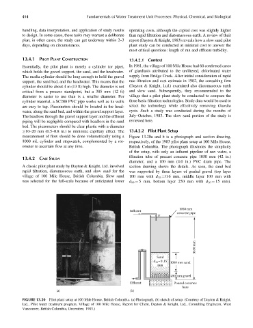
measurement of flow should be done volumetrically using a Figure 13.20a and b is a photograph and section drawing,
1000 mL cylinder and stopwatch, complemented by a rot- respectively, of the 1983 pilot plant setup at 100 Mile House,
ometer to ascertain flow at any time. British Columbia. The photograph illustrates the simplicity
of the setup, with only an influent pipeline of raw water, a
filtration tube of precast concrete pipe 1050 mm (42 in.)
13.4.2 CASE STUDY
diameter, and a 100 mm (4.0 in.) PVC drain pipe. The
A classic pilot plant study by Dayton & Knight, Ltd. involved section drawing shows the details. As seen, the sand bed
rapid filtration, diatomaceous earth, and slow sand for the was supported by three layers of graded gravel (top layer
village of 100 Mile House, British Columbia. Slow sand 100 mm with d 10 ¼ 0.6 mm, middle layer 100 mm with
was selected for the full-scale because of anticipated lower d 10 ¼ 5 mm, bottom layer 250 mm with d 10 ¼ 15 mm).
1050 mm
Influent
concrete pipe
3530 mm
Sand
d =0 .15 1060 mm sand
10
mm
450 mm gravel
Effluent Poured concrete
base
(a) (b)
FIGURE 13.20 Pilot plant setup at 100 Mile House, British Columbia. (a) Photograph, (b) sketch of setup. (Courtesy of Dayton & Knight,
Ltd., Pilot water treatment program, Village of 100 Mile House, Report for Client, Dayton & Knight, Ltd., Consulting Engineers, West
Vancouver, British Columbia, December, 1983.)