
Page 457 - Fundamentals of Water Treatment Unit Processes : Physical, Chemical, and Biological
P. 457
412 Fundamentals of Water Treatment Unit Processes: Physical, Chemical, and Biological
and to resand the bed when the time arrives. The access for
scraping and resanding should be adequate so that the operators
can complete the tasks in a normal working fashion. The sand
removal and placement should not require abnormal body
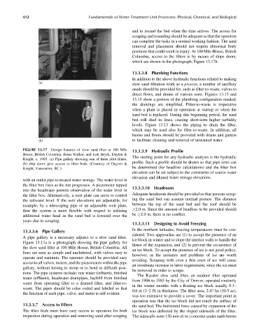
positions that could result in injury. At 100 Mile House, British
Columbia, access to the filters is by means of ships doors,
which are shown in the photograph, Figure 13.17b.
13.3.3.8 Plumbing Functions
In addition to the above hydraulic functions related to making
(a)
slow sand filtration work as a process, a number of ancillary
needs should be provided for, such as filter-to-waste, valves to
direct flows, and drains of various sorts. Figures 13.13 and
13.15 show a portion of the plumbing configuration needed;
the drawings are simplified. Filter-to-waste is imperative
when a plant is placed in operation at startup or when the
sand bed is replaced. During this beginning period, the sand
bed will shed its fines, causing short-term higher turbidity
levels. Figure 13.13 shows the piping to drain the filter,
which may be used also for filter-to-waste. In addition, all
basins and floors should be provided with drains and gutters
(b) to facilitate cleaning and removal of unwanted water.
FIGURE 13.17 Design features of slow sand filter at 100 Mile 13.3.3.9 Hydraulic Profile
House, British Columbia. Brian Walker, and Jack Bryck, Dayton &
The starting point for any hydraulic analysis is the hydraulic
Knight, c. 1985. (a) Pipe gallery showing one of three pilot filters,
profile. Such a profile should be drawn so that pipe sizes can
(b) ship doors give access to filter beds. (Courtesy of Dayton &
Knight, Vancouver, BC.) be determined (for headloss calculations) and the filter box
elevation can be set subject to the constraints of source water
elevation and filtered water storage elevations.
with an outlet pipe to treated water storage. The water level in
the filter box rises as the run progresses. A piezometer tapped
13.3.3.10 Headroom
into the headwater permits observation of the water level in
the filter box. Alternatively, a weir plate can serve to control Adequate headroom should be provided so that persons scrap-
ing the sand bed can assume normal posture. The distance
the tailwater level. If the weir elevations are adjustable, for
between the top of the sand bed and the roof should be
example, by a telescoping pipe or an adjustable weir plate,
2.0 m. Since the amount of headloss to be provided should
then the system is more flexible with respect to utilizing
additional water head as the sand bed is lowered over the be 2.0 m, there is no conflict.
years due to scraping.
13.3.3.11 Designing to Avoid Freezing
In the northern latitudes, freezing temperatures must be con-
13.3.3.6 Pipe Gallery
sidered. Two approaches are (1) to accept the presence of an
A pipe gallery is a necessary adjunct to a slow sand filter.
ice block in winter and to slope the interior walls to handle the
Figure 13.17a is a photograph showing the pipe gallery for
thrust of the expansion, and (2) to prevent the occurrence of
the slow sand filter at 100 Mile House, British Columbia. All
an ice block. To accept the presence of ice is not good policy,
lines are seen as simple and uncluttered, with valves easy to
however, as the nuisance and problems of ice are worth
operate and maintain. The operator should be provided easy
avoiding. Scraping with even a thin crust of ice will cause
access to all valves, meters, and the piezometers within the pipe
an inordinate increase in labor requirement, since the ice must
gallery, without having to stoop or to bend in difficult posi-
be removed in order to scrape.
tions. The pipe systems include: raw water (influent), finished
The Kassler slow sand filter, an outdoor filter operated
water (effluent), headwater drainpipes, backfill from finished
from 1906 to 1985 by the City of Denver, operated routinely
water from operating filter to a drained filter, and filter-to-
in the winter months with a floating ice block usually 0.3–
waste. The pipes should be color coded and labeled so that
0.6 m (1–2 ft) in thickness. The filter area, 2.47 ha (10.5 ac),
the function of each pipe, valve, and meter is self-evident.
was too extensive to provide a cover. The important point in
operation was that the ice block did not touch the surface of
13.3.3.7 Access to Filters the sand bed. The horizontal force caused by expansion of the
The filter beds must have easy access to operators for both ice block was deflected by the sloped sidewalls of the filter.
inspection during operation and removing sand after scraping The sidewalls were 150 mm (6 in.) concrete under earth berms