
Page 452 - Fundamentals of Water Treatment Unit Processes : Physical, Chemical, and Biological
P. 452
Slow Sand Filtration 407
(2) to distribute the raw water without erosion of the sand bed;
(3) to collect water uniformly from the filter; (4) to drain the
headwater for sand bed scraping; (5) to install an overflow
weir below the level of the top of the filter box; (6) to measure
the flow to the filter; (7) to control the flow through the filter;
(8) to measure headloss through the filter bed; (9) to provide
for a variety of plumbing needs, such as filter-to-waste, drains,
directing flows, filling the dry bed from the bottom, etc.; and
(10) to avoid negative pressures within the sand bed. Most of
these functions may be performed by the raw water distribu-
tion manifold=valve system or the drainage system.
13.3.2.1 Backfilling after Scraping
After scraping, the dewatered filter must be backfilled with
filtered water through the underdrain system. Backfilling can
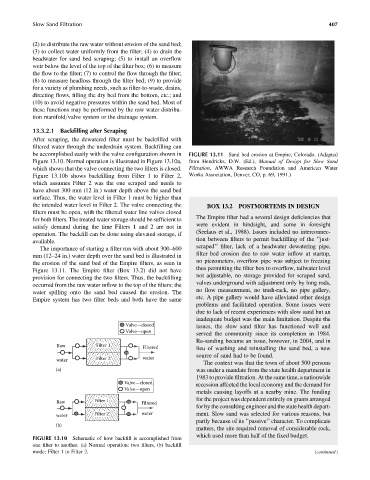
be accomplished easily with the valve configuration shown in FIGURE 13.11 Sand bed erosion at Empire, Colorado. (Adapted
Figure 13.10. Normal operation is illustrated in Figure 13.10a, from Hendricks, D.W. (Ed.), Manual of Design for Slow Sand
which shows that the valve connecting the two filters is closed. Filtration, AWWA Research Foundation and American Water
Figure 13.10b shows backfilling from Filter 1 to Filter 2, Works Association, Denver, CO, p. 69, 1991.)
which assumes Filter 2 was the one scraped and needs to
have about 300 mm (12 in.) water depth above the sand bed
surface. Thus, the water level in Filter 1 must be higher than
the intended water level in Filter 2. The valve connecting the BOX 13.2 POSTMORTEMS IN DESIGN
filters must be open, with the filtered water line valves closed
The Empire filter had a several design deficiencies that
for both filters. The treated water storage should be sufficient to
were evident in hindsight, and some in foresight
satisfy demand during the time Filters 1 and 2 are not in
(Seelaus et al., 1988). Issues included no interconnec-
operation. The backfill can be done using elevated storage, if
tion between filters to permit backfilling of the ‘‘just-
available.
scraped’’ filter, lack of a headwater dewatering pipe,
The importance of starting a filter run with about 300–600
filter bed erosion due to raw water inflow at startup,
mm (12–24 in.) water depth over the sand bed is illustrated in
no piezometers, overflow pipe was subject to freezing
the erosion of the sand bed of the Empire filters, as seen in
thus permitting the filter box to overflow, tailwater level
Figure 13.11. The Empire filter (Box 13.2) did not have
not adjustable, no storage provided for scraped sand,
provision for connecting the two filters. Thus, the backfilling
valves underground with adjustment only by long rods,
occurred from the raw water inflow to the top of the filters; the
water spilling onto the sand bed caused the erosion. The no flow measurement, no trash-rack, no pipe gallery,
Empire system has two filter beds and both have the same etc. A pipe gallery would have alleviated other design
problems and facilitated operation. Some issues were
due to lack of recent experiences with slow sand but an
inadequate budget was the main limitation. Despite the
Valve—closed issues, the slow sand filter has functioned well and
Valve—open
served the community since its completion in 1984.
Re-sanding became an issue, however, in 2004, and in
Raw Filter 1 Filtered lieu of washing and reinstalling the sand bed, a new
source of sand had to be found.
water Filter 2 water
The context was that the town of about 500 persons
(a) was under a mandate from the state health department in
1983 to provide filtration. At the same time, a nationwide
Valve—closed
recession affected the local economy and the demand for
Valve—open
metals causing layoffs at a nearby mine. The funding
Raw Filter 1 Filtered for the project was dependent entirely on grants arranged
for by the consulting engineer and the state health depart-
water Filter 2 water ment. Slow sand was selected for various reasons, but
partly because of its ‘‘passive’’ character. To complicate
(b)
matters, the site required removal of considerable rock,
which used more than half of the fixed budget.
FIGURE 13.10 Schematic of how backfill is accomplished from
one filter to another. (a) Normal operation: two filters, (b) backfill
mode: Filter 1 to Filter 2. (continued )