
Page 450 - Fundamentals of Water Treatment Unit Processes : Physical, Chemical, and Biological
P. 450
Slow Sand Filtration 405
13.3.1.2 Number of Cells 6.0 m
Every slow sand filter should have two or more cells so that
when one is out of service for scraping or other reasons, one
filter bed can continue producing sufficient water for the
community. Whether more than two filter beds are used
depends upon the time required for scraping and capital
costs. As discussed above, the number of cells directly affects
how the system operates and performs as a system.
Example 13.2 Number of Cells Comprising 43.0 m
a Filter Bed Filter No. 1 Filter No. 2 Filter No. 3
Using the data from Empire, calculate an upper limit area
for a single cell for a slow sand filter.
1 Local conditions—assumptions
Assume that the filter bed can be out of operation for 16 h,
and that three persons are available for scraping. Also
assume that 10 h are needed to drain the headwater (the
time required at Empire), and 4 h are needed to put the filter
back into operation, leaving 2 h available for scraping. Also
2
assume scraping rate ¼ 38 m =person=h (the rate at Empire). Finished
Chlorine P
2 Calculate maximum area of a cell
Chlorine contact water
Operations building
2
A cell ¼ (scraping rate in m =person=h) (No: of persons) Raw water
(Hours allotted to scraping)
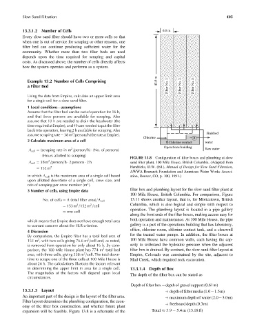
FIGURE 13.8 Configuration of filter boxes and plumbing at slow
2
A cell ¼ 38 m =person=h 2 persons 2h sand filter plant, 100 Mile House, British Columbia. (Adapted from
¼ 152 m 2 Hendricks, D.W. (Ed.), Manual of Design for Slow Sand Filtration,
AWWA Research Foundation and American Water Works Associ-
in which A cell is the maximum area of a single cell based ation, Denver, CO, p. 100, 1991.)
upon allotted downtime of a single cell, crew size, and
2
rate of scraping per crew member (m ).
filter box and plumbing layout for the slow sand filter plant at
3 Number of cells, using Empire data
100 Mile House, British Columbia. For comparison, Figure
13.11 shows another layout, that is, for Moricetown, British
No: of cells ¼ A (total filter area)=A cell
2
2
¼ 153 m =152 m =cell Columbia, which is also logical and simple with respect to
operation. The plumbing layout is located in a pipe gallery
one cell
along the front ends of the filter boxes, making access easy for
both operation and maintenance. At 100 Mile House, the pipe
which means that Empire does not have enough total area
to warrant concern about the HLR criterion. gallery is a part of the operations building that has laboratory,
office, chlorine room, chlorine contact tank, and a clearwell
4 Discussion
for the treated water pumps. In addition, the filter boxes at
By comparison, the Empire filter has a total bed area of
2
2
153 m , with two cells giving 76.6 m =cell and, as noted, 100 Mile House have common walls, each having the cap-
is removed from operation for only about 16 h. By com- acity to withstand the hydraulic pressure when the adjacent
2
parison, the 100 Mile House plant has 774 m total bed filter box is drained. By contrast, the slow sand filter layout at
2
area, with three cells, giving 258 m =cell. The total down- Empire, Colorado was constrained by the site, adjacent to
time to scrape one of the three cells at 100 Mile House is Mad Creek, which required rock excavation.
about 24 h. The calculations illustrate the factors relevant
in determining the upper limit in area for a single cell. 13.3.1.4 Depth of Box
The magnitudes of the factors will depend upon local The depth of the filter box can be stated as
circumstances.
Depth of filter box¼depth of gravel support (0:61m)
13.3.1.3 Layout þ depth of filter media (1:0 1:5m)
An important part of the design is the layout of the filter area. þ maximum depth of water (2:0 3:0m)
Filter layout determines the plumbing configuration, the econ-
þ freeboard depth (0:3m)
omy of the filter box construction, and whether future plant
expansion will be feasible. Figure 13.8 is a schematic of the Total 3:9 5:4 m(13:18 ft)