
Page 453 - Fundamentals of Water Treatment Unit Processes : Physical, Chemical, and Biological
P. 453
408 Fundamentals of Water Treatment Unit Processes: Physical, Chemical, and Biological
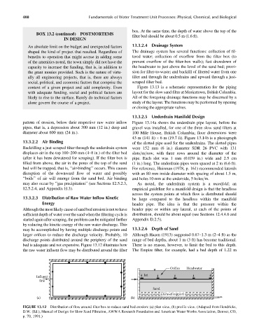
box. At the same time, the depth of water above the top of the
BOX 13.2 (continued) POSTMORTEMS
filter bed should be about 0.5 m (1.6 ft).
IN DESIGN
An absolute limit on the budget and unexpected factors 13.3.2.4 Drainage System
shaped the kind of project that resulted. Regardless of The drainage system has several functions: collection of fil-
benefits to operation that might accrue in adding some tered water; collection of overflow from the filter box (to
of the amenities noted, the town simply did not have the prevent overflow of the filter-box walls); fast drawdown of
capacity to increase the funding, that is, in addition to the headwater to just above the level of the sand bed; provi-
the grant monies provided. Such is the nature of virtu- sion for filter-to-waste; and backfill of filtered water from one
ally all engineering projects, that is, there are always filter and through the underdrains and upward through a just-
social, political, and economic factors that comprise the scraped filter bed.
context of a given project and add complexity. Even Figure 13.13 is a schematic representation for the piping
with adequate funding, social and political factors are layout for the slow sand filter at Moricetown, British Columbia.
likely to rise to the surface. Rarely do technical factors All of the foregoing drainage functions may be discerned by a
alone govern the course of a project. study of the layout. The functions may be performed by opening
or closing the appropriate valves.
13.3.2.5 Underdrain Manifold Design
pattern of erosion, below their respective raw water inflow Figure 13.14a shows the underdrain pipe layout, before the
pipes, that is, a depression about 300 mm (12 in.) deep and gravel was installed, for one of the three slow sand filters at
diameter about 600 mm (24 in.). 100 Mile House, British Columbia; floor dimensions were
43 m (141 ft) 6 m (19.7 ft). Figure 13.14b is a photograph
13.3.2.2 Air Binding of the slotted pipe used for the underdrains. The slotted pipes
Backfilling a just-scraped filter through the underdrain system were 152 mm (6 in.) diameter SDR 26 PVC with 131
displaces air in the top 100–200 mm (4–8 in.) of the filter bed slots=m=row, with three rows around the diameter of the
(after it has been dewatered for scraping). If the filter box is pipe. Each slot was 1 mm (0.039 in.) wide and 2.5 cm
filled from above, the air in the pores of the top of the sand (1 in.) long. The underdrain pipes were spaced at 2 m (6.6 ft).
bed will be trapped, that is, ‘‘air-binding’’ occurs. This causes For reference, Huisman (1978, p. 161) recommended laterals
disruption of the downward flow of water and possibly with an 80 mm inside diameter with spacing of about 1.5 m,
‘‘boils’’ of air will emerge from the sand bed. Air binding and holes 10 mm at the underside, 5 holes=m.
may also occur by ‘‘gas precipitation’’ (see Sections 12.5.2.3, As noted, the underdrain system is a manifold;an
12.5.2.4, and Appendix H.3). empirical guideline for a manifold design is that the headloss
across the system points at which flow is distributed should
13.3.2.3 Distribution of Raw Water Inflow Kinetic be large compared to the headloss within the manifold
Energy header pipe. The idea is that the pressure within the
Although the most likely cause of sand bed erosion is not to have header pipe or within any lateral, at each of the points of
sufficient depth of water over the sand when the filtering cycle is distribution, should be about equal (see Sections 12.4.4.6 and
started again after scraping, the problem can be mitigated further Appendix D.2.5).
by reducing the kinetic energy of the raw water discharge. This
may be accomplished by having multiple discharge points and 13.3.2.6 Depth of Sand
larger orifices to reduce the discharge velocity. Probably, 10 Although Hazen (1913) suggested 0.67–1.3 m (2–4 ft) as the
discharge points distributed around the periphery of the sand range of bed depths, about 1 m (3 ft) has become traditional.
bed is adequate and not expensive. Figure 13.12 illustrates how There is no reason, however, to limit the bed to this depth.
the raw water influent flow may be distributed around the filter The Empire filter, for example, had a bed depth of 1.22 m
Orifice Headwater
Jet
Influent
line
Sand
Gravel support
(a) (b)
FIGURE 13.12 Distribution of flow around filter box to reduce sand bed erosion: (a) plan view, (b) profile view. (Adapted from Hendricks,
D.W. (Ed.), Manual of Design for Slow Sand Filtration, AWWA Research Foundation and American Water Works Association, Denver, CO,
p. 70, 1991.)