
Page 442 - Fundamentals of Water Treatment Unit Processes : Physical, Chemical, and Biological
P. 442
Slow Sand Filtration 397
construction funds may be spent within the community. Some
appurtenances also may be obtained locally. For example, an
orifice plate may be used for flow measurement, with fabri-
cation by a local machinist. Valves and underdrain pipe lat-
erals must be ordered from vendors.
13.1.2.6 Contextual Factors
Slow sand has special appeal for small communities, regard-
less of country. The reasons include: (1) being a passive
process, skilled operation is not required; (2) keeping
capital and operating costs local helps the economy of the
community; (3) requiring more labor, for larger installations,
employs more persons, which may be a societal objective;
and (4) the slow sand process is effective in removal of
organisms. For such reasons, the International Reference
Center (IRC) in Delft, the Netherlands, has done much
to promote slow sand in India, SE Asia, and Latin
America (Kerkhoven, 1979; van Dijk and Oomen, 1978;
van Markenlaan, 1981).
FIGURE 13.2 Comparisons between influent and effluent cartridge
filters (1 mm pore size) for slow sand filters at Empire, Colorado.
13.1.3 HISTORY
(Adapted from Hendricks, D.W. et al., Filtration of Giardia cysts and
other particles under treatment plant conditions, Research report on By 1800, the notion of filtration to purify drinking water had
water treatment and operations, AWWA Research Foundation, Den- evolved in several cities in Great Britain (Baker, 1948,
ver, CO, February, 1988; Hendricks, D.W. (Ed.), Manual of Design
pp. 64–115). The filters of that period were designed for
for Slow Sand Filtration, AWWA Research Foundation and Ameri-
downward, upward, or horizontal flow, with the latter being
can Water Works Association, Denver, CO, p. 31, 1991.)
prevalent. All of these filters ‘‘failed,’’ since there was no
means for in-place cleaning. Two cleaning methods that even-
storage placement, and rebuilding the sand bed for a filter tually evolved were: (1) backwash and (2) scraping the sur-
area of 2.47 ha (10.5 ac) (Beer and Dice, 1982; Hendricks face. The former was patented in 1791 and the technology
et al., 1991, p. 92) with filter runs of 3–6 months. became known as ‘‘mechanical’’ filtration. The patent was
utilized in 1827 by Robert Thom to engineer the first instal-
13.1.2.5 Materials lation for municipal use at Geenock, Scotland (p. 91); his
The materials for a slow sand filter are mostly sand, gravel, design was aided by observing clogging of existing filters.
and concrete, which, for many installations, may be obtained James Simpson also observed existing filters (p. 93) but took a
locally. A local contractor may be available also. All of this different path. He noted that the detritus removed was at or
makes slow sand attractive economically since most of the just below the surface of the sand and so concluded that the
10 1000
Influent 100 Influent
Turbidity (NTU) 0.1 Effluent Coliforms (#/100 mL) 10
1
1
Effluent
0.01 0.1
0.01 0.1 1 5 10 20 30 50 70 80 90 95 99 99.9 99.99 0.01 0.1 1 5 10 20 30 50 70 80 90 95 99 99.9 99.99
(a) Percent (b) Percent
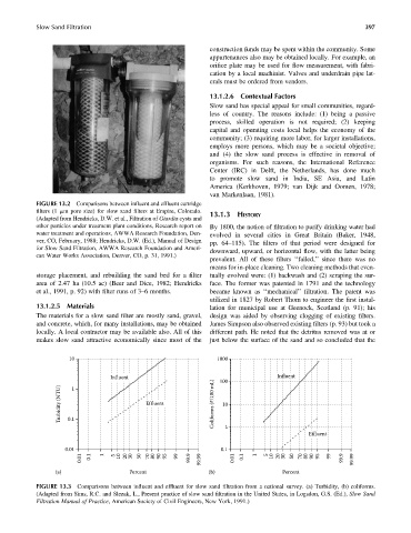
FIGURE 13.3 Comparisons between influent and effluent for slow sand filtration from a national survey. (a) Turbidity, (b) coliforms.
(Adapted from Sims, R.C. and Slezak, L., Present practice of slow sand filtration in the United States, in Logsdon, G.S. (Ed.), Slow Sand
Filtration Manual of Practice, American Society of Civil Engineers, New York, 1991.)