
Page 621 - Fundamentals of Water Treatment Unit Processes : Physical, Chemical, and Biological
P. 621
576 Fundamentals of Water Treatment Unit Processes: Physical, Chemical, and Biological
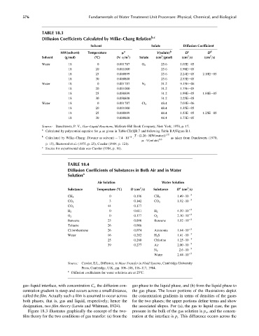
TABLE 18.3
Diffusion Coefficients Calculated by Wilke–Chang Relation b,c
Solvent Solute Diffusion Coefficient
MW(solvent) Temperature m a V(solute) b D c D d
2
2
2
3
Solvent (g=mol) (8C) (N s=m ) Solute (cm =gmol) (cm =s) (cm =s)
Water 18 0 0.001787 O 2 25.6 1.03E 05
18 20 0.001000 25.6 1.98E 05
18 25 0.000899 25.6 2.24E 05 2.10E 05
18 30 0.000808 25.6 2.53E 05
Water 18 0 0.001787 N 2 31.2 9.15E 06
18 20 0.001000 31.2 1.75E 05
18 25 0.000899 31.2 1.99E 05 1.88E 05
18 30 0.000808 31.2 2.25E 05
Water 18 0 0.001787 Cl 2 48.4 7.03E 06
18 20 0.001000 48.4 1.35E 05
18 25 0.000899 48.4 1.53E 05 1.25E 05
18 30 0.000808 48.4 1.73E 05
Source: Danckwerts, P. V., Gas–Liquid Reactions, McGraw-Hill Book Company, New York, 1970, p. 17.
a
Calculated by polynomial equation for m as given in Table CD=QR.7 and following Table B.9=Figure B.1.
T (2:26 MW(water)) 1=2
b 8
Calculated by Wilke–Chang: D(water as solvent) ¼ 7:4 10 as taken from Danckwerts (1970,
m V(solute) 0:6
p. 15), Sherwood et al. (1975, p. 25), Cussler (1984, p. 121).
c
Source for experimental data was Cussler (1984, p. 16).
TABLE 18.4
Diffusion Coefficients of Substances in Both Air and in Water
Solution a
Air Solution Water Solution
2
2
a
Substance Temperature (8C) D (cm =s) Substance D (cm =s)
0 0.196 1.49 10 5
CH 4 CH 4
3 0.142 1.92 10 5
CO 2 CO 2
CO 2 44 0.177
0 0.611 4.50 10 5
H 2 H 2
O 2 0 0.177 O 2 2.10 10 5
Benzene 25 0.096 Benzene 1.02 10 5
Toluene 26 0.086
Chlorobenzene 26 0.074 Ammonia 1.64 10 5
Water 16 0.282 H 2 S 1.41 10 5
5
25 0.260 Chlorine 1.25 10
39 0.277 Air 2.00 10 5
2.6 10 5
N 2
Water 2.44 10 5
Source: Cussler, E.L., Diffusion, in Mass Transfer in Fluid Systems, Cambridge University
Press, Cambridge, U.K., pp. 106–108, 116–117, 1984.
a
Diffusion coefficients for water solutions are at 258C.
gas–liquid interface, with concentration C i , the diffusion con- gas phase to the liquid phase, and (b) from the liquid phase to
centration gradient is steep and occurs across a small distance, the gas phase. The lower portions of the illustrations depict
called the film. Actually such a film is assumed to occur across the concentration gradients in terms of densities of the gases
both phases, that is, gas and liquid, respectively; hence the for the two phases; the upper portions define terms and show
designation, two-film theory (Lewis and Whitman, 1924). the associated slopes. For (a), the gas to liquid case, the gas
Figure 18.3 illustrates graphically the concept of the two- pressure in the bulk of the gas solution is p o , and the concen-
film theory for the two conditions of gas transfer: (a) from the tration at the interface is p i . This difference occurs across the