
Page 641 - Fundamentals of Water Treatment Unit Processes : Physical, Chemical, and Biological
P. 641
596 Fundamentals of Water Treatment Unit Processes: Physical, Chemical, and Biological
18.3.2.3.1 Coarse-Bubble Aeration ing the surface energy to create a bubble; very little is due to
frictional loss. In general the headloss due to bubble formation
Bubbles sizes in the range 6–10 mm are called ‘‘coarse-bub-
is 5 cm water (0.49 Pa), with range 8–51 cm water (0.78–
bles’’ and are produced by orifices in plates or pipes. In
5.00 kPa). The membrane slots are flexible and enlarge as air
general, oxygen transfer efficiencies are about 6%–7%
pressure increases and close if the airflow is zero, preventing
(Morgan and Bewtra, 1959, 1960, 1963). The coarse-bubble
backflow of water and are resistant to fouling. The air side
diffusers came into vogue mostly to avoid the need for air
fouling is considered less important than the water side foul-
filters and to avoid clogging, both associated with fine-bubble
ing (Boyle et al., 1989, p. 4).
diffusers.
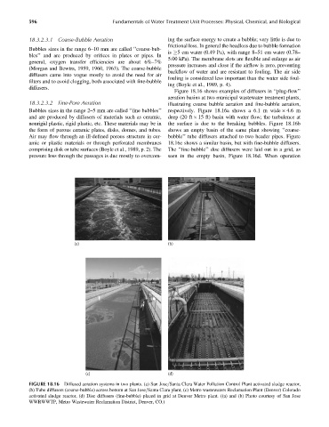
Figure 18.16 shows examples of diffusers in ‘‘plug-flow’’
aeration basins at two municipal wastewater treatment plants,
18.3.2.3.2 Fine-Pore Aeration illustrating coarse bubble aeration and fine-bubble aeration,
Bubbles sizes in the range 2–5 mm are called ‘‘fine bubbles’’ respectively. Figure 18.16a shows a 6.1 m wide 4.6 m
and are produced by diffusers of materials such as ceramic, deep (20 ft 15 ft) basin with water flow; the turbulence at
nonrigid plastic, rigid plastic, etc. These materials may be in the surface is due to the breaking bubbles. Figure 18.16b
the form of porous ceramic plates, disks, domes, and tubes. shows an empty basin of the same plant showing ‘‘coarse-
Air may flow through an ill-defined porous structure in cer- bubble’’ tube diffusers attached to two header pipes. Figure
amic or plastic materials or through perforated membranes 18.16c shows a similar basin, but with fine-bubble diffusers.
comprising disk or tube surfaces (Boyle et al., 1989, p. 2). The The ‘‘fine-bubble’’ disc diffusers were laid out in a grid, as
pressure loss through the passages is due mostly to overcom- seen in the empty basin, Figure 18.16d. When operation
(a) (b)
(c) (d)
FIGURE 18.16 Diffused aeration systems in two plants. (a) San Jose=Santa Clara Water Pollution Control Plant activated sludge reactor,
(b) Tube diffusers (coarse-bubble) across bottom at San Jose=Santa Clara plant, (c) Metro wastewaters Reclamation Plant (Denver) Colorado
activated sludge reactor, (d) Disc diffusers (fine-bubble) placed in grid at Denver Metro plant. ((a) and (b) Photo courtesy of San Jose
WWRWWTP, Metro Wastewater Reclamation District, Denver, CO.)