
Page 642 - Fundamentals of Water Treatment Unit Processes : Physical, Chemical, and Biological
P. 642
Gas Transfer 597
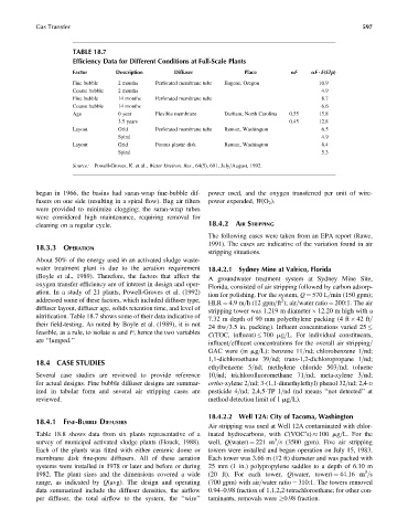
TABLE 18.7
Efficiency Data for Different Conditions at Full-Scale Plants
Factor Description Diffuser Place aF aF ? E(STp)
Fine bubble 2 months Perforated membrane tube Eugene, Oregon 10.9
Coarse bubble 2 months 4.9
Fine bubble 14 months Perforated membrane tube 8.7
Coarse bubble 14 months 6.6
Age 0 year Flexible membrane Durham, North Carolina 0.55 15.8
3.5 years 0.45 12.8
Layout Grid Perforated membrane tube Renton, Washington 6.5
Spiral 4.9
Layout Grid Porous plastic disk Renton, Washington 8.4
Spiral 5.3
Source: Powell-Groves, K. et al., Water Environ. Res., 64(5), 691, July=August, 1992.
began in 1966, the basins had saran-wrap fine-bubble dif- power used, and the oxygen transferred per unit of wire-
fusers on one side (resulting in a spiral flow). Bag air filters power expended, W(O 2 ).
were provided to minimize clogging; the saran-wrap tubes
were considered high maintenance, requiring removal for
cleaning on a regular cycle. 18.4.2 AIR STRIPPING
The following cases were taken from an EPA report (Rawe,
1991). The cases are indicative of the variation found in air
18.3.3 OPERATION
stripping situations.
About 50% of the energy used in an activated sludge waste-
water treatment plant is due to the aeration requirement 18.4.2.1 Sydney Mine at Valrico, Florida
(Boyle et al., 1989). Therefore, the factors that affect the
A groundwater treatment system at Sydney Mine Site,
oxygen transfer efficiency are of interest in design and oper-
Florida, consisted of air stripping followed by carbon adsorp-
ation. In a study of 21 plants, Powell-Groves et al. (1992)
tion for polishing. For the system, Q ¼ 570 L=min (150 gpm);
addressed some of these factors, which included diffuser type, 2
HLR ¼ 4.9 m=h (12 gpm=ft ); air=water ratio ¼ 200:1. The air
diffuser layout, diffuser age, solids retention time, and level of
stripping tower was 1.219 m diameter 12.20 m high with a
nitrification. Table 18.7 shows some of their data indicative of 7.32 m depth of 90 mm polyethylene packing (4 ft 42 ft=
their field-testing. As noted by Boyle et al. (1989), it is not
24 ftw=3.5 in. packing). Influent concentrations varied 25
feasible, as a rule, to isolate a and F; hence the two variables C(TOC, influent) 700 mg=L. For individual constituents,
are ‘‘lumped.’’ influent=effluent concentrations for the overall air stripping=
GAC were (in mg=L): benzene 11=nd; chlorobenzene 1=nd;
1,1-dichloroethane 39=nd; trans-1,2-dichloropropane 1=nd;
18.4 CASE STUDIES
ethylbenzene 5=nd; methylene chloride 503=nd; toluene
Several case studies are reviewed to provide reference 10=nd; trichlorofluoromethane 71=nd; meta-xylene 3=nd;
for actual designs. Fine bubble diffuser designs are summar- ortho-xylene 2=nd; 3-(1,1-dimethylethyl) phenol 32=nd; 2,4-D
ized in tabular form and several air stripping cases are pesticide 4=nd; 2,4,5-TP 1=nd (nd means ‘‘not detected’’ at
reviewed. method detection limit of 1 mg=L).
18.4.2.2 Well 12A: City of Tacoma, Washington
18.4.1 FINE-BUBBLE DIFFUSERS
Air stripping was used at Well 12A contaminated with chlor-
Table 18.8 shows data from six plants representative of a inated hydrocarbons, with C(VOC’s) 100 mg=L. For the
3
survey of municipal activated sludge plants (Houck, 1988). well, Q(water) ¼ 221 m =s (3500 gpm). Five air stripping
Each of the plants was fitted with either ceramic dome or towers were installed and began operation on July 15, 1983.
membrane disk fine-pore diffusers. All of these aeration Each tower was 3.66 m (12 ft) diameter and was packed with
systems were installed in 1978 or later and before or during 25 mm (1 in.) polypropylene saddles to a depth of 6.10 m
3
1982. The plant sizes and the dimensions covered a wide (20 ft). For each tower, Q(water, tower) ¼ 44.16 m =s
range, as indicated by Q(avg). The design and operating (700 gpm) with air=water ratio ¼ 310:1. The towers removed
data summarized include the diffuser densities, the airflow 0.94–0.98 fraction of 1,1,2,2-tetrachloroethane; for other con-
per diffuser, the total airflow to the system, the ‘‘wire’’ taminants, removals were 0.98 fraction.