
Page 25 - Gas Purification 5E
P. 25
Introduction 15
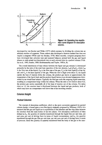
Bottom /
y2
Figure 1-6. Operating line-equilib-
I I rium curve diagram for absorption
x2 column.
developed by von Stockar and Wilke (1977) which operates by dividing the column into an
arbitrary number of segments. These authors also developed a shortcut method that does not
require a computer (Wilke and von Stockar, 1978). More recently, computer programs have
been developed that calculate heat and material balances around both the gas and liquid
phases on each actual (not theoretical) tray or each selected slice in a packed column (Vick-
ery et al., 1992; Seader, 1989; Krisbnamurthy and Taylor, 1985A, B).
The overall distribution of heat release between the liquid and gas streams is determined
primarily by the ratio of the total heat capacities of the two streams, L&JGMC,, where LM
is the flow rate of the liquid, GM is the flow rate of the gas, C, is the heat capacity of the liq-
uid, and is the heat capacity of the gas. When the ratio is high (over about 2), the liquid
carries the heat of reaction down the column, the product gas leaves at approximately the
temperature of the liquid feed, and the product liquid leaves at an elevated temperature deter-
mined by an overall heat balance. Typically the feed gas cools the outgoing liquid somewhat,
resulting in a temperature bulge within the column. When the ratio is low (below about OS),
the product gas carries essentially all of the heat of reaction out of the column. For ratios
close to 1.0, the reaction heat is distributed between the liquid and gas products, both of
which may leave at a temperature well above that of the incoming streams.
Column Height
Packed Columns
The concept of absorption coefficient, which is the most convenient approach for packed
column design, is based upon a twc-film theory originally proposed by Whitman (1923). It is
assumed that the gas and liquid are in equilibrium at the interface and that thin films separate
the interface from the main bodies of the two phases. Two absorption coefficients are then
defined as kL, the quantity of material transferred through the liquid film per unit time, per
unit area, per unit of driving force in terms of liquid concentration; and k, the quantity
transferred through the gas film per unit time, per unit ma, per unit of driving force in terms
of pressure. Since the quantity of material transferred from the body of the gas to the inter-