
Page 39 - Gas Purification 5E
P. 39
Introduction 29
Packing Sue, in. Maximum Liquid Loading, gpdft2
% 25
1 40
1% 55
2 60
3% 125
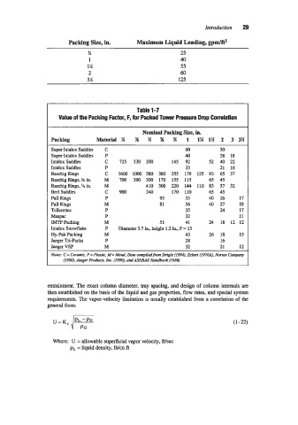
Table 1-7
Value of the Packing Factor, F, for Packed Tower Pressure Drop Correlation
Nominal Packing Si, in.
Packing Material % % % W % 1 1% 1% 2 3 3%
Super Intalox Saddles C 60 30
Super Intalox Saddles P 40 28 18
Intalox Saddles C 725 330 200 145 92 52 40 22
Intalox Saddles P 33 21 16
Raschig Rings C 1600 10oO 580 380 255 179 125 93 65 37
Raschig Rings, !& in. M 700 390 300 170 155 115 65 45
Raschig Rings, K in. M 410 300 220 144 110 83 57 32
Berl Saddles C 900 240 170 110 65 45
Pail Rings P 95 55 40 26 17
Pall Rings M 81 56 40 27 18
Tellerettes P 35 24 17
bPac P 32 21
IMTF' Packing M 51 41 24 18 12 12
Intalox Snowflake P Diameter 3.7 in., height 1.2 in., F = 13
Hy-Pak Packing M 43 26 18 15
Jaeger Tri-Packs P 28 16
Jaeger VSP M 32 21 12
Nom: C = Ceramic, P = Plastic. M = MetaL Data compiledfrom Suigle (1994). Ecken (1970A), Norton Company
(1990). Jaeger Products, Inc. (1990). and ASHRAE Handbook (1988)
entrainment. The exact column diameter, tray spacing, and design of column intemals are
then established on the basis of the liquid and gas properties, flow rates, and special system
requirements. The vap-velocity limitation is usually established from a correlation of the
general form:
(1-22)
Where: U = allowable superficial vapor velocity, ft/sec
pL = liquid density, lb/cu ft