
Page 322 - gas transport in porous media
P. 322
Chapter 19: In Situ Measurement of Induced Flux
Injection of 321
clean gas Gas collection
Surface
and analysis
Probe
External Teflon tube
Inner Teflon tube
Gas
In Situ void
flux
Sacrificial tip
Ground water
COVERED BY US PATENTS
Injection of
clean gas Gas collection
Surface
and analysis
Well
External Teflon tube
Inner Teflon tube
Packers
Gas
flux
Soil formation
Permeable zone around well
Groundwater
COVERED BY US PATENTS
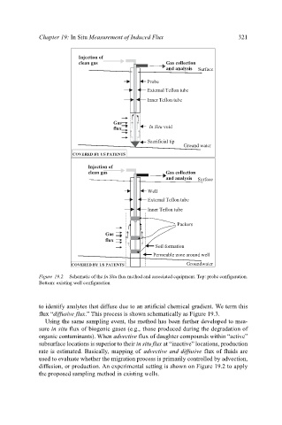
Figure 19.2. Schematic of the In Situ flux method and associated equipment. Top: probe configuration.
Bottom: existing well configuration
to identify analytes that diffuse due to an artificial chemical gradient. We term this
flux “diffusive flux.” This process is shown schematically as Figure 19.3.
Using the same sampling event, the method has been further developed to mea-
sure in situ flux of biogenic gases (e.g., those produced during the degradation of
organic contaminants). When advective flux of daughter compounds within “active”
subsurface locations is superior to their in situ flux at “inactive” locations, production
rate is estimated. Basically, mapping of advective and diffusive flux of fluids are
used to evaluate whether the migration process is primarily controlled by advection,
diffusion, or production. An experimental setting is shown on Figure 19.2 to apply
the proposed sampling method in existing wells.