
Page 199 - Geothermal Energy Renewable Energy and The Environment
P. 199
186 Geothermal Energy: Renewable Energy and the Environment
condensing back to a liquid as the pressure drops. At this point, the cycle has been completed and
the working fluid is again available for heating.
ThermodynamIcs oF heaT pUmps
Heat pump technology employed in ground source systems is based on the same thermodynamic
principles as that employed by binary geothermal power generation systems using a Rankine cycle.
The obvious differences between the systems are the conditions and energy densities that are uti-
lized, and the fluid used in the heat transfer process.
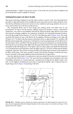
The nonaqueous fluids used in heat pumps have boiling points well below that of cool
groundwaters. In Figure 10.4 the pressure–enthalpy diagram for propane is shown, contoured for
temperature. Also shown is the boundary between the liquid and liquid–vapor field for water under
these pressure-enthalpy conditions, for comparison. Generally, the working fluid heated by interac-
tion with the ground will be between 5°C and 15°C (the light-gray field in Figure 10.4). The work-
ing fluid will transfer its heat to the fluid in the heat pump at the heat exchanger on the right side
of Figure 10.3. The fluid in the heat pump at that point will be at approximately 0°C and about 100
kPa (the actual temperature and pressure will depend on the heat pump design and the fluid used in
the heat pump). Hence, the fluid in the heat pump will increase in temperature at constant pressure,
following the arrow pointing to the right in the dark-gray field in Figure 10.4. When the liquid in the
heat pump reaches the temperature of the liquid–vapor two-phase region, the liquid will absorb heat
at a constant pressure and temperature while the liquid vaporizes. This will continue until the fluid is
completely vaporized. The amount of energy absorbed will depend upon the heat of vaporization of
the fluid. At that point, if the vapor remains in contact with the heat exchanger, it will become super
heated, meaning it will acquire additional heat beyond the heat of vaporization.
Once the vapor has formed, it is compressed to a pressure about 10 times that at which it vaporized
(arrow in the Gas field in Figure 10.4). The vapor then moves through a heat exchanger in the room
or building, losing heat at a constant pressure, crossing back through the two phase Liquid + Gas
field. As this happens, the fluid gives up its heat of vaporization and the vapor condenses back to a
liquid (long arrow in Figure 10.4 pointing to the left).
10 5
10 4 Water
Liquid
10 3 Pressure 50°C
window
0°C
kPa 10 2
–50°C
Gas
10 1
10 0 –100°C
Liquid + Gas
10 –1
0 200 400 600 800
Enthalpy (kJ/kg)
FIGUre 10.4 Enthalpy–pressure diagram for propane showing the two-phase liquid-gas region. For refer-
ence, the low-temperature limb of the liquid boundary for the water system is also shown (see Figure 3.8 for
details of the water system).