
Page 198 - Geothermal Energy Renewable Energy and The Environment
P. 198
Low Temperature Geothermal Resources: Ground Source Heat Pumps 185
D A
C
Fluid from
Cool liquid Cold liquid closed loop
Valve
Compressor
Hot gas Warm gas
High pressure side Low pressure side
(approximately 1500 kPa (approximately 100 kPa or
or 15 bars) 1 bar)
B
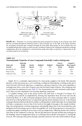
FIGUre 10.3 Schematic of a ground-coupled heat pump designed for heating. In the heating mode, fluid
that has circulated through the subsurface enters a heat exchange coil on the right of the figure and heats
the circulating refrigerant that is pumped through the heat pump. Heat pumps are also available that can
accomplish heating and cooling, in which case the circulation scheme for the refrigerant and the heat exchange
configuration allow the refrigerant to switch between modes that either accept heat or deposit heat in the
circulating fluid in the closed loop.
Table 10.1
Thermodynamic properties of some compounds potentially Useful as refrigerants
molecular heat of constant p
name and weight density melting T boiling T Vaporization heat capacity
Formula (g/mol) (kg/m3) (°c) (°c) (kJ/kg) (kJ/kg-k)
102.03 1206 −101 −26.6 215.9 0.853
R134a H 2 FC-CF 3
44.096 582 −187.7 −42.1 425.31 1.701
Propane C 3 H 8
72.15 626 28 344.4 2.288
Isopentane C 5 H 12 −160
Figure 10.3 is a schematic representation of a heat pump coupled to the Earth. The principle
elements of the heat pump are a coil containing a refrigerant fluid that has a boiling point that is
lower than that of the local subsurface, a compressor, a pressure reduction valve, and a capability to
exchange heat with a room (left of figure) and with the Earth (right of figure). The refrigerant that
is used varies by manufacturer (see Table 10.1 for characteristics of some commonly used refriger-
ants). These are now stipulated to be nonozone depleting compounds.
A complete heating cycle of the pump involves the path from A through D in Figure 10.3
(a cooling cycle could be accomplished by allowing heat deposition from the room side into the
closed loop fluid). At A, the cool liquid refrigerant passes into a heat exchanger where it acquires
heat from the working fluid that has circulated through the Earth’s thermal reservoir. If the thermal
exchange efficiency between the Earth and the circulating fluid is sufficiently high, the working fluid
will have a temperature close to that of the Earth at the depth of the pipe in the outside borehole.
Since the refrigerant has a boiling temperature substantially below that of the local subsurface, the
refrigerant boils, becoming a gas as it flows through the coil. At B the gas pressure is increased by a
compression pump, resulting in an increase in the gas temperature, reflecting the fact that work has
been done by the compressor on the gas. The hot gas then passes through another heat exchanger in
the building, where its temperature drops as it exchanges heat with the room (point C), heating the
room air. The warm gas then passes through a pressure reduction valve (D), which results in the gas