
Page 231 - Geothermal Energy Renewable Energy and The Environment
P. 231
Direct Use of Geothermal Resources 219
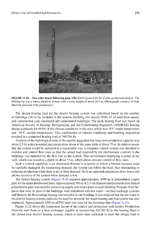
FIGUre 11.10 (See color insert following page 17.0..) Drill rig used for the Canby geothermal project. The
drilling rig was a rotary platform system with a tower height of about 18.5 m. (Photograph courtesy of Dale
Merrick and used with permission.)
The design heating load for the district heating system was calculated based on the number
of buildings (34) to be included in the system, building size (nearly 5000 m of total floor space),
2
and construction type (insulated and uninsulated buildings). The peak heating load was based on
American Society of Heating, Refrigerating and Air-Conditioning Engineers (ASHRAE) heating
design standards for 99.6% of the climate conditions in the area, which was 18°C inside temperature
and −15°C outside temperature. This combination of climate conditions and building population
resulted in a computed heating load of 389,784 J/s.
Analysis of the hydrological state of the aquifer suggested that long-term production capacity was
about 2.3 l/s with a potential maximum draw down of the water table of about 75 m. In order to assure
that the system would be operated in a sustainable way, a computer control system was installed to
monitor and control flow rates so that the actual load required by the thermostatic controls in the
buildings was matched by the flow rate in the system. This necessitated emplacing a pump in the
well, which was seated at a depth of about 73 m, which allows precise control of flow rates.
Such a control capability is an important element in a system in which a limited resource must
be carefully managed. By monitoring demand, the system can follow the load, thus eliminating or
reducing production when there is no or little demand. Such an approach minimizes draw down and
allows recovery of the system when demand is low.
The district heating system (Figure 11.11) required approximately 2050 m of preinsulated copper
pipe for the main distribution lines. Approximately 550 m of 2.5 cm diameter preinsulated cross-linked
polyethylene pipe was used for connecting supply and return pipes to each building. Propane-fired fur-
naces that were in most of the buildings were retrofitted with hot water—air heat exchange systems
and blowers. In-floor radiant heating was installed in one building. It was realized that the hot water in
the district heating system could also be used for domestic hot water heating and that system was also
emplaced. Approximately 1550 m of PVC pipe was used for the discharge line (Figure 11.11).
Figure 11.12 shows the component layout of the control and production well facility. Production
from the well flows to a heat exchanger capable of transferring 433,745 J/s to the heating fluid in
the closed-loop district heating system, which is more than sufficient to meet the design load of