
Page 232 - Geothermal Energy Renewable Energy and The Environment
P. 232
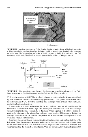
220                          Geothermal Energy: Renewable Energy and the Environment


                                District heating
                                  distribution
                                    line

                                             Discharge line


                                     500 meters


                                                       Discharge point

            FIGUre 11.11  Air photo of the town of Canby, showing the district heating layout (white lines), production
            well location and discharge line (black line). Individual buildings served by the district heating system are
            outlined in white. The location of the production well, which is co-located with the control facility and GAC
            filter system, is indicated. (Modified from diagram provided by Dale Merrick. With permission.)

                                      Heat
                                    exchanger   Backup
                         Production              boiler                Hot water
                            well
                                                                        supply

                                                                       Hot water
                                                                        return
                                                                Hot water
                                                                 return


                                                      GAC
                                    Heat               filter
                                  exchanger                          Discharge

            FIGUre 11.12  Schematic of the production well, distribution system, and disposal system for the Canby
            district heating system. (Modified from an original by Dale Merrick. With permission.)
            2.3 l/s at a temperature of 88°C. When the heat exchanger operates optimally, it is capable of heat-
            ing 38°C return water from the district heating system to 66°C. The geothermal fluid that leaves
            the heat exchanger at 43°C flows to a secondary heat exchanger which preheats return water, thus
            maximizing heat transfer and use.
              It was found that optimal performance for the heat exchanger was not achieved because the
            water has an iron content of about 3 mg/l. The iron deposits on the surfaces of the heat exchanger
            plates, reducing the thermal conductivity of the plates. Within a period of about three months the
            heat transfer efficiency of the primary heat exchanger drops by about 15%, requiring that the heat
            exchanger be disassembled and cleaned. This periodic maintenance has been incorporated into the
            operational schedule for the system.
              Experience has shown that, on average, the district heating system load is about half that of the
            design load. Since the computer monitoring and control system functions on a load-following basis,
            this has allowed the resource to be minimally affected. Experience has shown that it is only for brief
            winter periods that the design load must be met. On a few occasions, flow rates as high as 2.5 l/s