
Page 70 - Geothermal Energy Systems Exploration, Development, and Utilization
P. 70
46 2 Exploration Methods
S V S V S V
S h
S h
S h
S H
S H S H
(a)
S V S V S V
S h S h S h
S H S H
S H
(b)
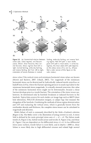
Figure 2.2 (a) Geometrical relation between faulting, strike-slip faulting, and reverse fault-
stress axes, stress regimes, and fracture ing regime. Red drill path is least stable;
planes. Brown: shear fractures; blue: ten- green drill path is most stable. In strike-slip
sile fractures. Stress regimes from left to regimes, the most stable drill path depends
right: normal faulting, strike-slip faulting, on the stress ratios of S V and S H .(Please
and reverse faulting. (b) From left to right, find a color version of this figure on the
orientation of tensile fractures in normal color plates.)
stress value if the vertical stress and minimum horizontal stress values are known
(Moeck and Backers, 2007; Zoback, 2007). The magnitude of the minimum
horizontal stress can be determined by hydraulically induced tensile mini-fracs or
leakoff tests (LOTs), where the fracture opening pressure is nearly equivalent to the
minimum horizontal stress magnitude. In critically stressed reservoirs, this value
of the minimum horizontal stress might not be determinable, because a shear
fracture develops prior to a tensile fracture. The orientation of the stress tensor can,
however, be determined only by borehole breakouts or induced fractures in the
borehole. Typical data sources for such studies are image logs such as BHTV (bore
hole televiewer), FMI/UBI (formation imager), or caliper logs that measure the
elongation of the borehole. Combining the methods of stress regime determination
and LOT and evaluating the vertical stress, which is generally known from the
overburden density and thickness, the complete stress tensor can be calculated in
magnitude and direction.
Brittle failure of rock is commonly described by the Mohr–Coulomb criterion
(Figure 2.3a). The Mohr circle is the illustration of acting stresses in rock. A stress
field is defined by the main principal stress axes s1 > s2 > s3. The failure mode
tensile (A, Figure 2.3a), hybrid tensile (shear and tensile; B, Figure 2.3a), and shear
(C, Figure 2.3a) are dependent on the differential stress s1–s3. In low differential
stress (near surface), tensile failure is most likely, and in depths >2000 m, shear
failure is more likely due to high differential stresses and related high normal